AC Clock(  for 2027)
 AC Clock( for 2027) |
In Development.
This project positions itself between the well-defined ACES project descriptions and your self-directed ISPs. This undertaking provides a sequenced outline of concepts to research and support with prototype development in parallel. Wherever possible, obtain scope traces and develop Falstad simulations to support your research and prototypes. For those ACES considering Electrical Engineering this one's especially applicable and insightful.
Clocks are an ACES passion.
We've created all sorts over the decades.
There's one approach we haven't tried - until now.
The ACES AC Clock Project
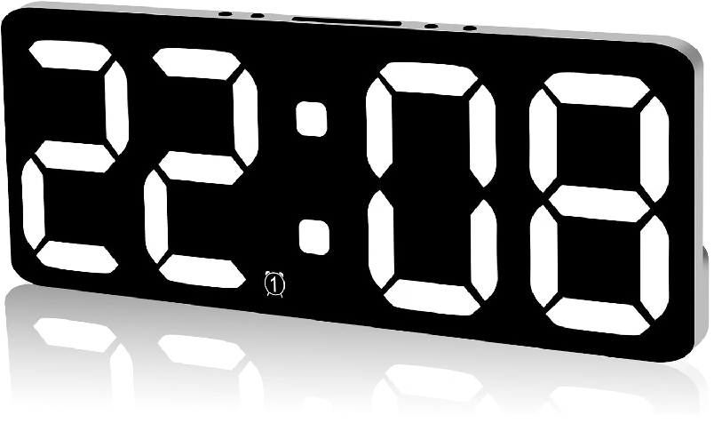 ACES clock projects in the past have used various strategies for their time base. RC charge/discharge cycles and crystals are the common options. While inexpensive, these sources can be less than accurate in the shoft run and vulnerable to significant drifting in the long run (typically due to temperature variations) with no autocorrection facility. There is, as luck would have it, an interesting self-correcting alternative.
The vast majority of project undertakings in our ACES program rely on Direct Current (DC) for their power source. Although this is the natural source for batteries and the default source from most wall adapters, this is not the current supplied to our homes from the power companies - that's Alternating Current (AC). This project explores the conversion and application of AC to useful DC.
Outline
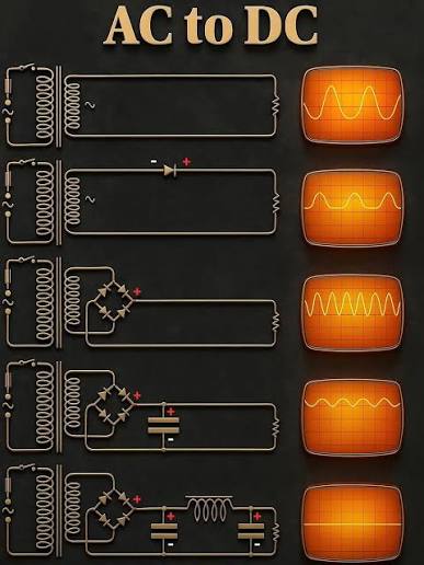 1. Alternating Current (AC) vs Direct Current (DC). Explain the difference.
2. The Power Grid
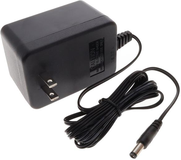
3. AC/AC Wall Adapter
 The Best Protection: Resettable Fuse
| IDEAL Power AC/AC Wall Mounted Adapter |
FNIRSi: 2C53T Hand Held Scope and Multimeter |
|---|---|
 |
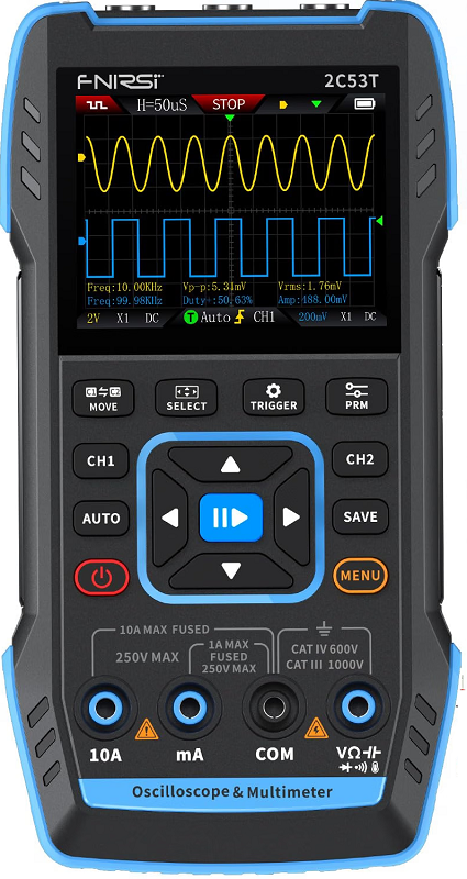 |
3. FNIRSI 2C53T. You have been lent an FNIRSI 2C53T handheld Oscilloscope and Multimeter for the duration of this project (above, right). It comes with a number of accessories that I'd ask that you keep CAREFUL track of and return complete. Familiarize yourself with it.
 CAUTION: Do NOT plug the probes of the 2C53T directly into a wall socket!
The digital multimeter function is rated up to 750V AC using the standard shrouded banana-plug test leads.
While the internal circuitry can technically read 120V or 240V AC,
safety guidelines for live mains work advise against relying on uncertified budget meters for household electrical outlets.
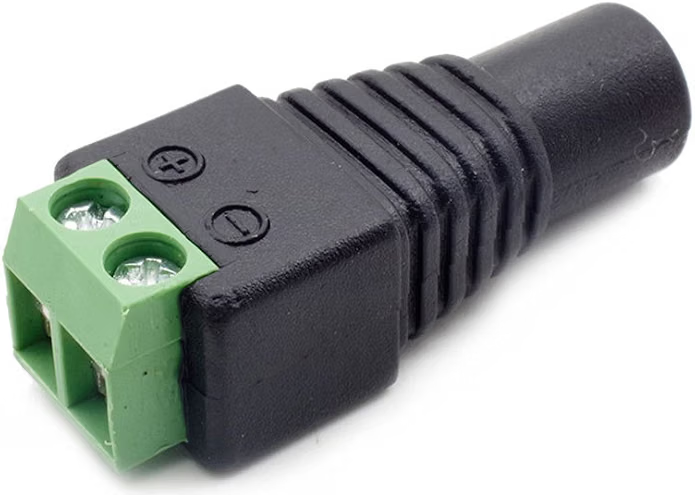
4. Female Power Connector
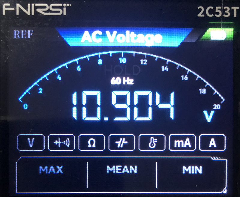
| Female Power Connector | FNIRSi: 2C53T as Multimeter |
|---|---|
 |
 |
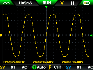
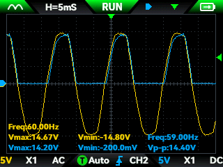
5. 2C53T Oscilloscope
| 9 VAC (RMS) | Half Wave Rectifier |
|---|---|
 |
 |
6. Rectification. To exploit both the power and frequency charateristics of your AC waveform the signal must be reshaped to interface smoothly with your microcontroller.
| Bridge Rectifier (Full Wave Rectifier) | |
|---|---|
(Approximate) Concept Sequence (22 Classes in the Term)
| # | CONCEPT | Hardware | Software | Design | Soldering | COMPONENT | DER |
|---|---|---|---|---|---|---|---|
| 1 | A Quartz Crystal Oscillating Time Base |  |
 |
||||
| 2 | Capturing Crystal Oscillations and Frequency Division (External and TimerOne Interrupts) |
|
 |
||||
| 3 | The I2C Communication Bus (The Wire Library) |
|
|
 |
|||
| 4 | Breadboarding an I2C Bus with a TC74 Temperature Sensor and DS1307 RTC |
|
|
|
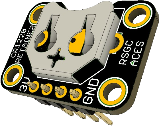 |
||
| 5 | DER: Scanning an I2C Bus | |
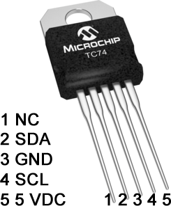 |
|
|||
| # | CONCEPT | Hardware | Software | Design | Soldering | COMPONENT | DER |
| 6 | SetDateTime and ReadDateTime Sketches | |
 |
||||
| 7 | Square Wave Frequency Settings | |
|
||||
| 8 | The ACES' DS1307 Breakout Board | |
|
 |
|||
| 9 | ACES ISP Breakout Boards | |
|
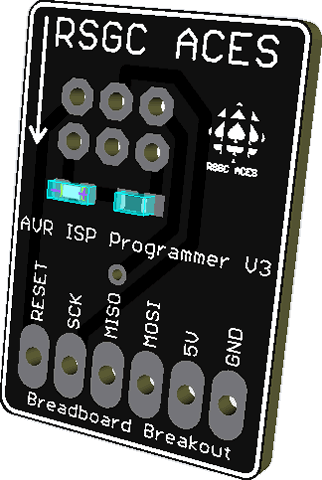 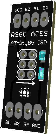 |
|||
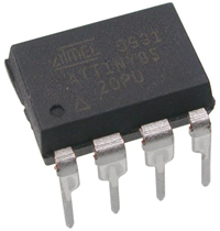
| 10 | MCU, Power & Size Considerations (mega328P, tiny84 or tiny85) |
|
|
 |
|||
| 11 | The Display Device (CA COM-09481? CC YSD-439AB4B?) |
|
|
 |
|||
| 12 | Arrays as Segment Maps for PoV | |
|
|
|||
| # | CONCEPT | Hardware | Software | Design | Soldering | COMPONENT | DER |
| 13 | Assembling and Testing your Prototype with RTC Data |
|
|
|
|
||
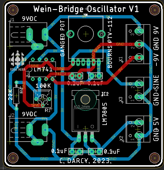
| 14 | Designing a PCB | |
|
|
 |
||
| 15 | Preparing a PCB for Manufacturing and Ordering | |
|
|
 |
||
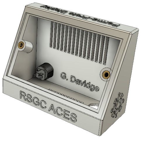
| 16 | Designing the PCB Encasement | |
|
 |
|||
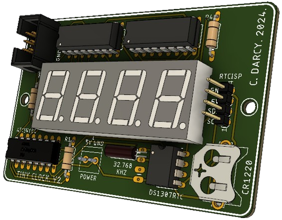
| 17 | PCB Assembly and Testing | |
|
|
|
 |
|
| 18 | Clock Case Assembly and Testing | ||||||
| 19 |
| SMT ATtiny85 Clock | THT ATtiny84 Clock |
|---|---|
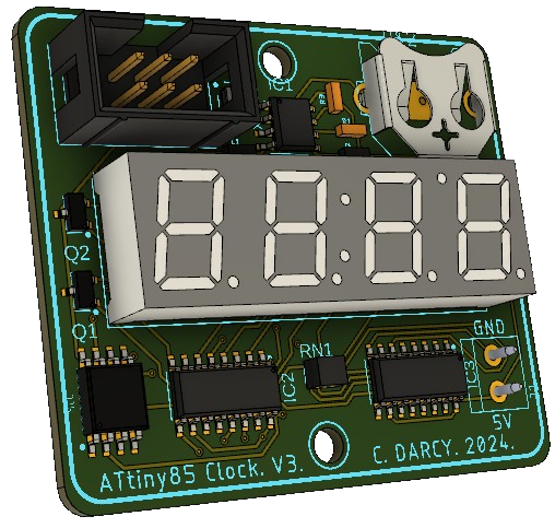 |
 |
 |
 |