Independent Study Projects. Please read our overview on why ACES pursue Independent Study Projects so vigorously.
2026-2027 ICS3U-E Independent Study Projects (ISPs) |
Independent Study Projects. Please read our overview on why ACES pursue Independent Study Projects so vigorously.
| Grade | Contribution to Final Mark |
|---|---|
10 |
30% |
11 |
40% |
12 |
60% |
For the bulk of your formal education you have been, and will continue to be, required to consume curriculum chosen for you by someone else. Hopefully you will put this knowledge and skill to good use in your future. However, jumping through someone else's hoops no longer secures future success. For that, you must put yourself in the driver's seat while in secondary school to both cultivate and demonstrate your own unique initiative, motivation, and passion. RSGC ACES program is explicitly built and tailored for you to foster these greater goals. Yes, there is much to learn but there are so many great projects to be undertaken and noble problems to be identified and solved that offer stimulating contexts within which to develop and refine your interests it will quickly seem more than worth the risk, effort, and cost.

 To my mind, the characteristics of a great project include such aspects as imagination, creativity, a degree of risk and, sometimes, even simplicity, to name a few. Check out the flashlight circuit 'board' this guy made out of little more that a piece of paper and a pencil? Simple, but inspiring.
Consider a problem that needs a solution. Boyan Slat did at age 17 when he was in high school; four years later he is
 cleaning up the world's oceans. (Update: January 9, 2019) So, dig in, think, dream, research, and explore possible project pursuits. Be discerning: don't accept the first thing that comes along. You'll be expected to maintain the progress of your ISP on your web page to enable everyone to follow your efforts so have your phone handy to at all times to capture the images of your journey. Be conscious of the fact that a multi-page summary of your project will appear in your DER after Presentation Day for more permanent record of your efforts. You may wish to take into account the ISP Evaluation document that will be applied on your Presentation Day.
Also, don't underestimate the value of an enterprise/entrepreneurial aspect to your project that could see a number of units of your project in the hands of future ACES, for sale in the Dragon's Lair or beyond, reaching an even a broader audience.
The 7Ps of a Successful ISP...Preparation > Proposal > Prototyping > Preview > Production > Presentation > Publication
2026-2027 TEJ3M Independent Study Projects
| ACE | ISP.Long (20%) Saturday October 31 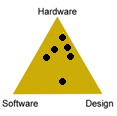 |
ISP.Medium (20%) Saturday January 31  |
|---|---|---|
| Proposals | ISP.Long Proposal |
ISP.Medum Proposal |
Barrett, J.
 |
Clicks Per Second (CPS) Tracker
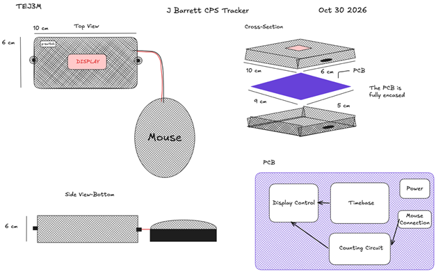
DESCRIPTION The CPS tracker would connect to a computer mouse and display the user’s clicks per second (CPS), using a gated frequency data type to display the clicks in the last second. This would use a 1 Hz time base and CMOS logic to accomplish this and return results on a seven-segment display, specifically using a CD4060/CD4013 time base, a CD4518 BCD counter, and CD4511 decoders. |
?
DESCRIPTION MCU HARDWARE SOFTWARE DESIGN MECHANICAL COMMUNCATION |
Breznitz, T.
 |
A Low-Level Chess Clock
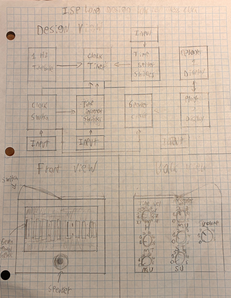
DESCRIPTION This project will be a chess clock containing a variety of changeable settings, with a focus on ease of use. It will have two decreasing counters running concurrently, where a switch at the top of the case decides which counter is active. It will have the functionality to set the beginning time that each player has at the start of the game. Additionally, it will have the capability to set an increment that will increase each players allotted time when the clock is pressed. Finally, every press of the clock will broadcast a signal to a speaker to play a beep, the volume can be changed by a rotary switch. |
?
DESCRIPTION MCU HARDWARE SOFTWARE DESIGN MECHANICAL COMMUNCATION |
Debow, J.
|
Satellite Receiver
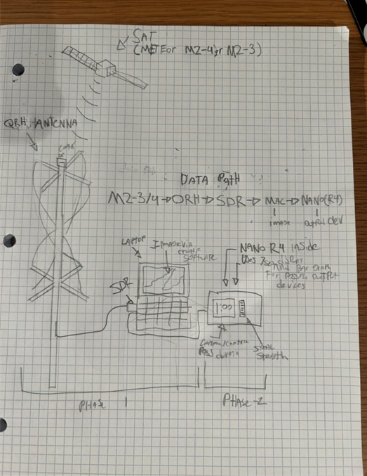
DESCRIPTION This project aims to create a device that can receive transmissions from Russian Meteor-class weather satellites, transmit them onto a laptop to receive images, and create a box that displays information about the pass and the reading, such as reading strength, time until reading, and time elapsed the readings will be collected using a QRH antenna that will be connected to a coax running to the laptop SDR and into software which converts the signal into photos and decodes it. |
?
DESCRIPTION MCU HARDWARE SOFTWARE DESIGN MECHANICAL COMMUNCATION |
Duckman, E.
|
555 IC Clock Watch
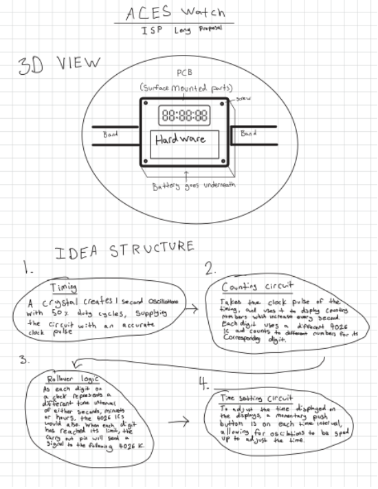
MCU None HARDWARE32.768 kHz crystal, CD4060 , CD4026BE, CD4081BE, CD4011BE, CD4001BE, CD4013BE, Common-Cathode 7-Segment LED Display. SOFTWARE None DESIGN EasyEDA will be used to create the PCB which will function the same as the prototype, just with surface mounted pieces to keep the build small. Additionally, Fusion will be used to create a small 3D printed case for the PCB. The case will feature slots for bands and a battery holder slot on the bottom. MECHANICAL N/A COMMUNCATION N/A |
?
DESCRIPTION MCU HARDWARE SOFTWARE DESIGN MECHANICAL COMMUNCATION |
Harrop, C.
|
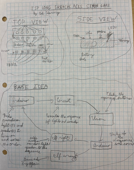
ACES Simon Game
DESCRIPTION This project aims to have a string of LEDs and speakers that come on in a random sequence, which the user will then have to replicate with buttons. First, it will be a sequence with only 1 LED turning on, then 2, then 3, etc. until failure, much like a Simon game. Potential addons include: difficulty levels (speeds), a reset button, a high score tracker, random button to LED connections to make it harder, an audio only setting, and many others. |
?
DESCRIPTION MCU HARDWARE SOFTWARE DESIGN MECHANICAL COMMUNCATION |
Herrmann, R.
|
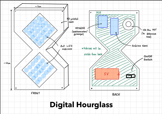
Interactive Digital Hourglass with Dynamic Physics
DESCRIPTION A battery-powered digital hourglass that simulates falling sand particles across two 8x8 LED matrices stacked on top of each other in a diamond shape. The user adjusts the timer duration (1 to 25 minutes) using a 10 kΩ potentiometer, with the setting visually displayed on the matrix. An MPU-6050 accelerometer tracks orientation and motion, dynamically updating the particle-grid sand physics so particles pool and slide naturally when tilted or flipped. The entire device runs with a battery built into the device (case). |
?
DESCRIPTION MCU HARDWARE SOFTWARE DESIGN MECHANICAL COMMUNCATION |
Johnson, T.
|
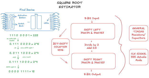
Square Root Estimator
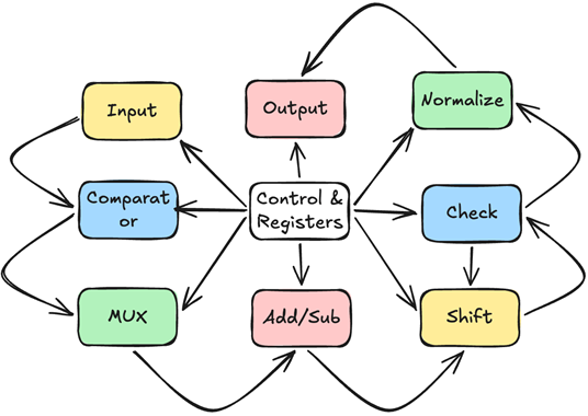
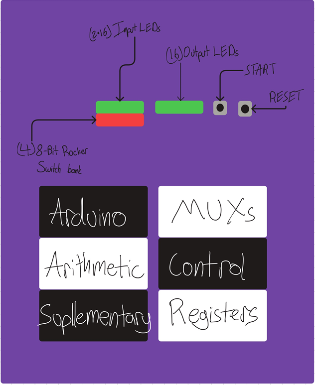
DESCRIPTION This circuit will generate a rough value for the square root of an 8-bit binary number. The algorithm used will be √(a×2^n )=(0.5+0.5a)×2^(n/2), which should have a relative error no larger than 6%. Although the output will not be very precise, this estimate could be useful in reducing the number of cycles for iterative square root algorithms. To accomplish this computation, the input will be shifted left to get the value of a within the proper range. A 4516 counter will store the number of bit-shifts, and the result will then be shifted right to reach the final result. The shifting will be performed by D flip-flops (IC 74HC74), along with 2-to-1 multiplexers (IC 74HC157) to take in the initial value. Together, these will form a makeshift Parallel-in/Parallel-Out shift register, driven by a clock signal from an astable 555 timer. The switch bank-controlled input and the output will be displayed via surface-mount LEDs. A push-button will activate the computation. Because this project is hardly standalone, both the inputs and outputs will have empty sockets to connect jumper wires. |
?
DESCRIPTION MCU HARDWARE SOFTWARE DESIGN MECHANICAL COMMUNCATION |
Lutke, T.
|
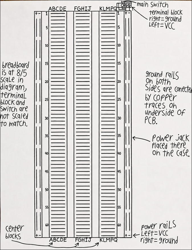
Breadboard
DESCRIPTION A PCB that is designed to hold metal strips for a breadboard layout modified with the addition of a third middle block, a power jack connected to booth side rails, and a central switch. and a 3D printed case that has holes for breadboard compatible components to snap into. Every hole will be spaced according to normal breadboard spacing (2.54mm)
SOFTWARE N/A DESIGN The PCB will be designed using EasyEDA and manufactured through JLCPCB. It will contain copper traces connecting a terminal block to both sets of power rails through a central on/off switch. The three middle breadboard blocks will be electrically independent from each other, each consisting of 60 rows each with five connected pins spaced 2.54 mm apart. The case will be designed in Fusion 360 and 3D printed using PLA plastic. It will contain an opening for the DC power jack and mounting points for the PCB. The breadboard will be a second 3D printed case made in Fusion 360 to hold the leads of components. The breadboard pins will be connected by metal strips mounted on the PCB MECHANICAL N/A COMMUNCATION N/A |
?
DESCRIPTION MCU HARDWARE SOFTWARE DESIGN MECHANICAL COMMUNCATION |
Mann Shaw, T.
|
2-bit Adder V2: Floating-Point Adder
MCU 328p (Nano R3) HARDWARE Arduino Nano R3 (ATmega328P), 74HC299 8-bit universal shift registers, 74HC283 4-bit binary adders, 74HC85 4-bit magnitude comparators, 74HC157 2:1 multiplexer, 74HC574 8-bit registers, 74HC74 D-type flip-flops, 74HC163 4-bit counters, 74HC138 decoders, AND gates, OR gates, NOT gates, XOR gates. SOFTWARE Arduino C DESIGN The finished project will be made on a PCB with a case protecting the insides, while small parts will be prototyped on a breadboard. MECHANICAL N/A COMMUNCATION UART Serial (via USB) and Digital GPIO (5 V HIGH/LOW signals)
|
?
DESCRIPTION MCU HARDWARE SOFTWARE DESIGN MECHANICAL COMMUNCATION UART Serial (via USB) and Digital GPIO (5 V HIGH/LOW signals) |
Morgan, W.
|
Pomodoro Timer
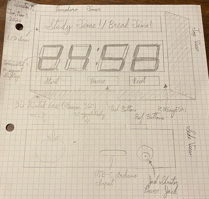
DESCRIPTION This project will be a digital Pomodoro timer that helps users organize their study sessions and breaks. It will use an Arduino Nano R4 to control a four-digital seven-segment display showing the countdown and an LCD screen displaying either “Study Time!” or “Break Time.” Physical buttons will allow users to start, pause, and reset timer, while programmed software will manage the countdown and automatically switch between study and break sessions. A buzzer will also sound when each session finishes. The project will combine breadboard electronics and Arduino programming to create an interactive productivity tool.
|
?
DESCRIPTION MCU HARDWARE SOFTWARE DESIGN MECHANICAL COMMUNCATION |
Mulcahy, E.
|
Digital Frequency Counter
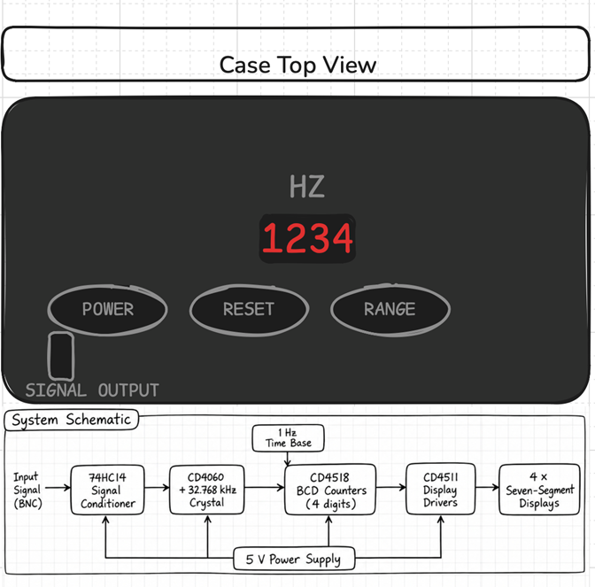
DESCRIPTION A standalone digital frequency counter that measures the frequency of electrical signals and displays the result on four seven-segment displays. The circuit uses a crystal-based timing circuit, CMOS counters and logic gates to measure the number of pulses received over a one-second interval. |
?
DESCRIPTION MCU HARDWARE SOFTWARE DESIGN MECHANICAL COMMUNCATION |
Quach, M.
|
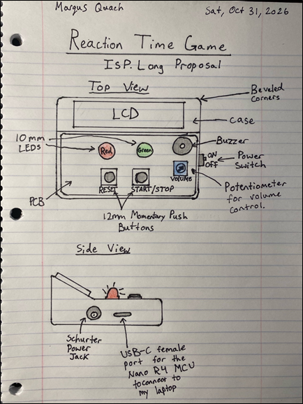
Reaction Time Game
DESCRIPTION This is a game that measures the user’s reaction time. There will be a red LED and green LED, acting like a traffic light, just without the yellow light. Once the green LED turns on, the user must press the “Stop” button as fast as they can. The amount of time elapsed in between the green LED turning on and the button being pressed is the user’s reaction time. If the user presses too early, the game will stop, and the LCD screen will tell the user to press the “Reset” button, which will be coded through an Arduino Nano R4 microcontroller. There will also be audio cues for certain actions in the game, in which the volume can be adjusted with a potentiometer. |
?
DESCRIPTION MCU HARDWARE SOFTWARE DESIGN MECHANICAL COMMUNCATION |
Sollazzo, A.
|
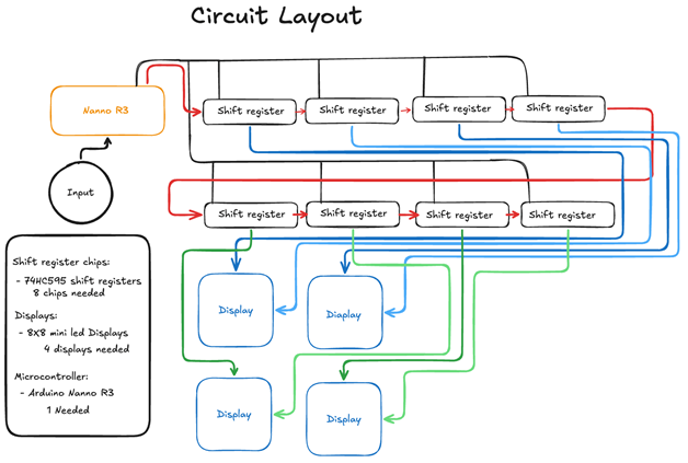
Flappy Bird
DESCRIPTION This project aims to create a playable game similar to the classic mobile flappy bird game. The user will press turn a potentiometer to move a dot up and down the screen, attempting to avoid obstacles. These will be displayed on four 8x8 mini LED displays arranged in a square grid. The obstacles will be randomly selected from a list of custom pieces created in the code. |
?
DESCRIPTION MCU HARDWARE SOFTWARE DESIGN MECHANICAL COMMUNCATION |
Tweedie, A.
|
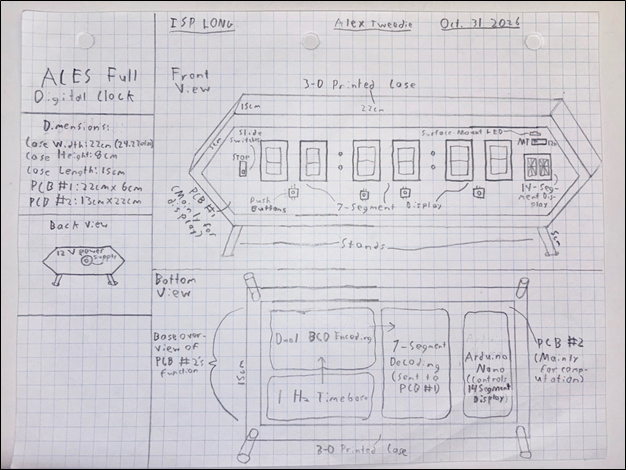
Full Digital Clock
DESCRIPTION The ACES Full Digital Clock, in essence, is a complicated extension of the Minute Minder. It will use a 1 Hz accurate timebase with a crystal oscillator to drive several BCD counters that will input into a 7-segment decoder to display an accurate 12-hour or military time. Time will be displayed using six 7-segment displays, like so: (HH : MM : SS). Time can be adjusted uses PBNOs that will all input voltage to their respective second, minute, or hours BCD counter to increase the clock by 1 unit. Military time and 12-hour time can be toggled using a SPDT switch that uses an AND, XOR and buffer gates to shortly create an input that feeds an S-R latch, allowing an alternating current to pass through and tick the hours clock exactly 12 times. An Arduino Nano R4 will also be used to configure a 14-Segment display that will either show AM or PM when a switch is flicked to display 12-hour time, or MT when military time is selected. |
?
DESCRIPTION MCU HARDWARE SOFTWARE DESIGN MECHANICAL COMMUNCATION |
Waterman, A.
|
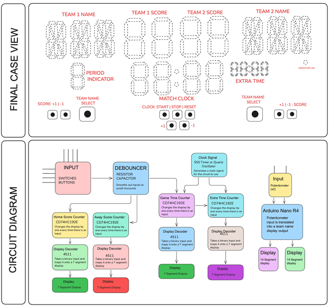
The Electronic Scoreboard
DESCRIPTION This project involves designing and building an electronic scoreboard using digital logic and electronic circuits. It will display information such as the time, score, period, extra time, and team names, with controls allowing the user to update the scoreboard manually. The initial design will focus entirely on hardware, with potential future extensions including microcontroller integration, a custom printed circuit board (PCB), and support for multiple sports. The goal of this project is to ????? |
?
DESCRIPTION MCU HARDWARE SOFTWARE DESIGN MECHANICAL COMMUNCATION |