| 2015-2016 TEI3M Engineering Tasks |
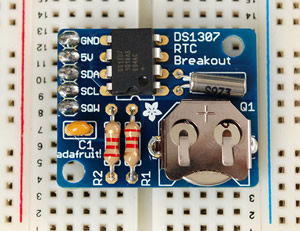
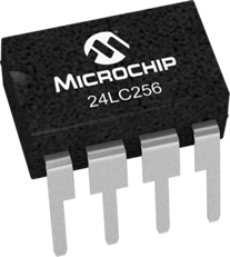
![]() I2C Data Logger. This project requires that you capture (multiple) sensor data over a period of time and log it with the Time/Date stamp from an I2C-compatible Real-Time Clock, to a I2C-compatible 256K EEPROM IC. The expectations for the project include a high build quality from the circuit itself to the encasement and access points. Finally, the data collected is to be displayed using a creative form of visualization. This presentation can be in Processing, a connectable graphics screen, Excel, or any other form of graphic depiction.
I2C Data Logger. This project requires that you capture (multiple) sensor data over a period of time and log it with the Time/Date stamp from an I2C-compatible Real-Time Clock, to a I2C-compatible 256K EEPROM IC. The expectations for the project include a high build quality from the circuit itself to the encasement and access points. Finally, the data collected is to be displayed using a creative form of visualization. This presentation can be in Processing, a connectable graphics screen, Excel, or any other form of graphic depiction.
There are a wide variety of analog sensors on the market as well as I2C sensors. The sooner you identify the concept/data you wish to log, the more time you'll have to secure an I2C sensor(s). Think creatively, simple monitoring of room temperature would demonstrate the least amount of imagination. On the other hand, a recent or upcoming lab from one of your science courses might be the perfect opportunity to apply sensor monitoring to. The Science department may even have their own sensing devices that you could interface with...
Some of the best projects will be based on a concept, principle, law, or research the engineer sets out to try to confirm or refute.
Design Considerations. In addition to CODE design decisions you make along the way as you develop your sketchs, this project requires that you make DATA design decisions as well. The use of the finite, byte- and page-oriented Serial EEPROM IC requires that you give deep consideration to the organization and design of the data you store for later retrieval. You are aware that the time and date data from the RTC is already in byte form, whereas the ADC data from analog read appears as two-byte ints [0-1024).
Note. You will present your work to your peers. In addition, this project will have a competitive side as each student will rank the other 19 projects in order of creativity, performance, build quality, etc. I'll aggregate the result and assign credit in relation to the results. Here is the evaluation page that will be used.
ER summary due Tuesday May 3 under the Subject Line: I2C Data Logger.
| I2C DS1307 RTC | I2C 24LC256 EEPROM | Sensors |
|---|---|---|
 |
 |
 |
![]() Medium ISP. See Description.
Medium ISP. See Description.
![]() Short ISP. See Description.
Short ISP. See Description.
 Microcontroller: ATmega328P or ATtiny85?
Submit to handin by midnight, Friday March 11. with the Subject Line: Audio Device.
You will have 3 minutes to present your project to your peers on Monday March 7 or Wednesday March 11.
![]() Persistence of Vision Challenge 2. Quite apart from the refreshing level of engagement that I witnessed in class on Monday, one student even wondered why we hadn't been doing this intense work since September? Hmmm....
Persistence of Vision Challenge 2. Quite apart from the refreshing level of engagement that I witnessed in class on Monday, one student even wondered why we hadn't been doing this intense work since September? Hmmm....
|
![]() Persistence of Vision Challenge 1.
Persistence of Vision Challenge 1.
 Reference: Exploring Arduino, pp. 41-59.
Tutorial: NYU: Serial Output from an Arduino to Processing
This project provides you with an opportunity to explore and showcase both your technical and creative skills. We have discussed the Model-View-Controller (MVC) design of project architecture. Your understanding of how to obtain and capture analog readings on the Arduino can produce the Model. Your experience in the use of the Processing language (Grade 10) to provide compelling visualizations will provide the View. All that remains is your ability to write great (efficient, documented, etc.) code to provide the Controller aspect of the MVC design to pull the project together.
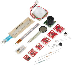
Sensors yielding varying analog voltage levels are available for monitoring almost any kind of natural phenomenon. Sparkfun offers a kit with a wide variety of them. Your toolkit comes with a few useful sensors that change resistance in response to external stimulation. The simplest one is the rotational actuation of the sweep arm of a potentiometer. P. Bagga used two of the these to manipulate the XY coordinates in his Grade 10 Etch-A-Sketch ISP. The LDR changes in response to incident light. Your TMP36 sensor yields varying voltage under changing temperature conditions. Your GP2Y0A41SK0F Sharp InfraRed distance measuring sensor is the most expensive sensor in your kit and could be used as a basis for a simple Theremin. Two of the more elaborate analog sensors from Sparkfun include the RGB Light Sensor and Triple Axis Gyro. The latter two are likely available at Creatron.
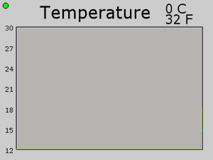
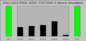
A few years ago, a Grade 11 ACE attached 6 temperature sensors to his Arduino, monitored the readings in round-robin style and placed streamed the data to the Serial port. Processing collected and recorded the data in a 6 by 100 matrix for his model, simultaneously presenting a view of the data below left. In 2015, R. Fletcher used the simulation of 5 TCRT5000L IR sensors below right to build his detection board to guide his Rover along a line.
| TMP36 Temperature Sensor View | TCRT5OOO IR Sensor View |
|---|---|
 |
 |
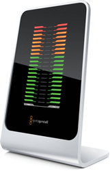
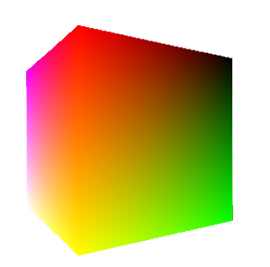
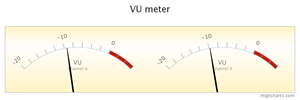 The two views above (line and bar) are two common ways to present the data. There are many others you have encountered either through your experience with Excel and/or various Presentation applications. The monitor on the first floor of See House presents a view of the solar data collected using dials, line charts and a thermometer for temperature. HighCharts.js offers web developers a package of JavaScript-based views. One of which is the VU Meter to the right. Ambitious ACES may wish to have an RGB Cube rotate in response to the motion of a Triple-Axis Gyro/Accelerometer.
Task.
 Using two or more sensors of your choosing (and any other components), imagine and develop an interesting MVC application that integrates Arduino with Processing to provide a compelling view of a sampling of real-world analog signals. Note: Arduino and Processing is a two-way street; each can communicate with each other :)
Do your research as soon as possible to allow time for the creativity to flood in.
SA, PB, NB, MB, JB, GC, TD, AE, OG, JG, NJ, MK, RK, KL, BL, MM, HM, RM, MP, ST
![]() Intersection Simulation. (Since many of you will be taking driving lessons in the near future it's a good time to review the workings of an intersection.) For your first 'common' project you are asked to develop a creative, Arduino based-simulation of an intersection that has, at the least, traffic lights in each of four directions. Your kit has red, yellow, and green LEDs. The simulation includes, of course, both software and hardware assets. Note. There are other features of a real-world intersection that you may wish to consider/investigate/simulate to enhance your Arduino knowledge and skills.
Intersection Simulation. (Since many of you will be taking driving lessons in the near future it's a good time to review the workings of an intersection.) For your first 'common' project you are asked to develop a creative, Arduino based-simulation of an intersection that has, at the least, traffic lights in each of four directions. Your kit has red, yellow, and green LEDs. The simulation includes, of course, both software and hardware assets. Note. There are other features of a real-world intersection that you may wish to consider/investigate/simulate to enhance your Arduino knowledge and skills.
Considerations
Engineering Report. Insert a page break at the end of your current ER, add TEI3M - Arduino centered on the page, and add a second page break before beginning your Intersection Simulation writeup for this project. Submit to handin by midnight, Sunday October 4. with the Subject Line: Intersection.
You will have 5 minutes to present your project to your peers on Tuesday October 6 and Thursday October 8.
![]() -
- ![]() Blink Variations. Modify the Blink sketch as required to accomplish each of the following progressively-challenging tasks. You are expected to write great code; the internet offers than enough bad code already; don't add to the supply.
Blink Variations. Modify the Blink sketch as required to accomplish each of the following progressively-challenging tasks. You are expected to write great code; the internet offers than enough bad code already; don't add to the supply.
Great code is beautiful and as much Art as it is Science.
It is
a tough, time-consuming and profoundly satisfying pursuit.
Do not be satisfied with code that simply works.