 Contents
 | RSGC ACES: Introduction to Computer Assisted Drawing (CAD) |
Contents
Before we start, I wish to recognize those individuals that willingly and patiently shared their passions for design with me so that, in turn, ACES could benefit from being provided with the tools to express their imagination and creativity in physical form.
First off, is Mr. P. Elia, a remarkably gifted artistic and generous individual with a vision that places design near the center of humanity in order to make the world a better place. Words can not express the deep impact he has had on our program, our students, and me, in particular.
Secondly, there are number of former ACES that went above and beyond in support of their peers and I through the years. Some, but not all, include, M. Elia, D. Dadyburjor, K. Fiset-Algarvio, J. Dolgin, J. Vretenar, L. Cassano, S. Appleyard and J. Rogan.
Our ACES program embraces the steep climb. We willingly accept the challenges for our four coveted domains: hardware, software, design, and communication. This page devotes itself to our design pursuits, in particular, computer assisted design and the physical production of these computer creations.
Like any other skill, proficiency requires dedication. Countless hours of research and iterative testing are required to gain competency. The deep satisfaction of small but regular breakthroughs is what propels you forward. The alternative is not to try and have nothing to show for it. ACES know better.
On the software side, ACES are asked to commit themselves to AutoDesk's free EAGLE and Fusion 360 applications. For production, the DES offers Prusa and Ultimaker 3D printers. Outsourcing of PCB manufacturing is primarily handled by JLCPCB and laser-cutting of acrylic is handled by Sawdust & Noise.
ACES are expected to finish their projects by installing their soldered circuits boards into some form of permanent housing. By the time you reach Grade 11 you've already benefited from a number of cases given to you. The first steps in creating your own custom 3D printed encasement for your circuits are the hardest. To ease you into it, like anything else, you can start with off-the-shelf designs.
ACES' Inventory of Ready-to-Print (RTP) Cases
 Over the past few years ACES have built up a good selection of case designs with a variety of useful features. Review a sample of designs at http://darcy.rsgc.on.ca/ACES/Enclosures/index.html. Wise ACES may wish to plan ahead by selecting an RTP case before committing to their circuit board to be soldered.
For custom case designs, ACES turn to Fusion 360. Start by downloading the application from AutoDesk. Once installed, ACES are encouraged to begin exploring our GitHub repository of case designs found at,
https://github.com/rsgcaces/ACESFusion360DesignFiles
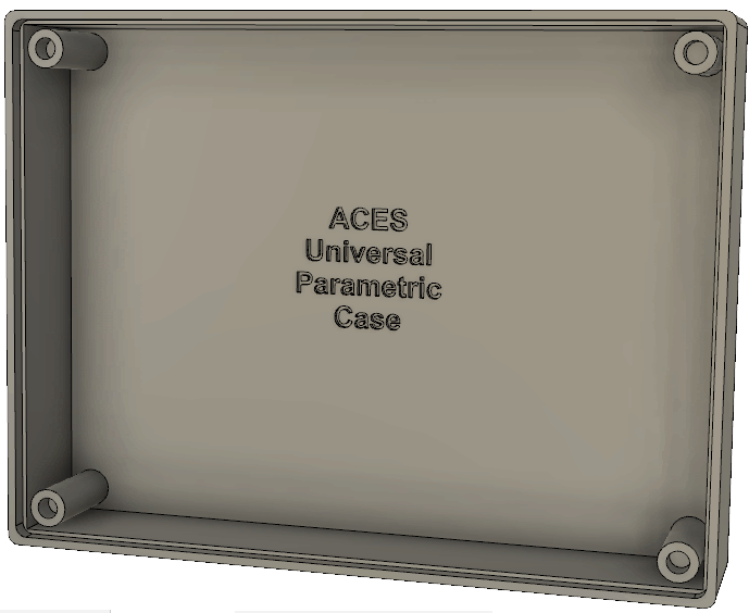
The first Fusion case design listed (ACESUnversalCase.f3d) is a parametrically-driven design (shown below) that the redesigner simply types in different values for the dimensions. Instruction will be provided to Grade 11s in class.
RSGC ACES' Perma-Proto Cases
Just like breadboards, the qualityof solderable PCBs varies. What might look like a bargain price can be anything but when it comes to the cost of time, parts and frustration. I recommend sticking with Adafruit's perma-proto boards. The quality is good and, depending on where you purchase them the price can be acceptable when you factor in your time. Furthermore, since they are laid out to match your breadboard, translating your prototype to one is relatively painless. Tip. Confirm continuity with your DMM after EVERY part is soldered. Do NOT wait unit the entire circuit has been soldered to debug. You'll regret it in time and cost. They are stackable though the use of standoffs. One shortcoming of theor design is that the holes on half size do not quite align with the holes on the full size. Aces could have designed better.
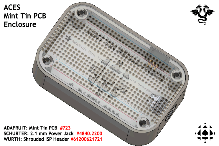
For this reason, I have developed custom cases that readily accept four perma-proto PCBs sizes (quarter, half, full and mint). I maintain an inventory of these so simply ask. One per ACE. This will be sufficient for most ACES. For those that are drawn to our design domain, I encourage you to download the Fusion 360 files from our repository and modify them as your imagination leads you.
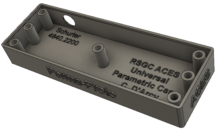
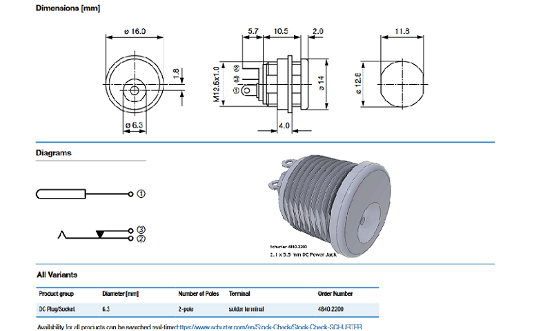
Pictured below is our full-size perma-proto V7 as if 2023 10 21 that was adapted from our ACES' Universal Parametric design. An optional opening for a Schurter 4840.2200 power jack has been included.
The second option for off-the-shelf case designs is Thingiverse. This is free repository of user-create designs for almost any project you can imagine. Type in PCB Case for starters and see what comes up.
ACES are strongly urged to develop custom enclosures for their PCBs. To this end I have provided specifications for common fastening accessories as a starting point for your CAD/CAM goals.
| Heat Set Insets | M3 Nuts | M3 Screws | Power Jack | Panel Mount PB |
|---|---|---|---|---|
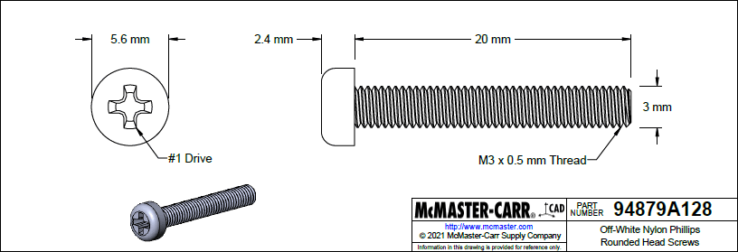
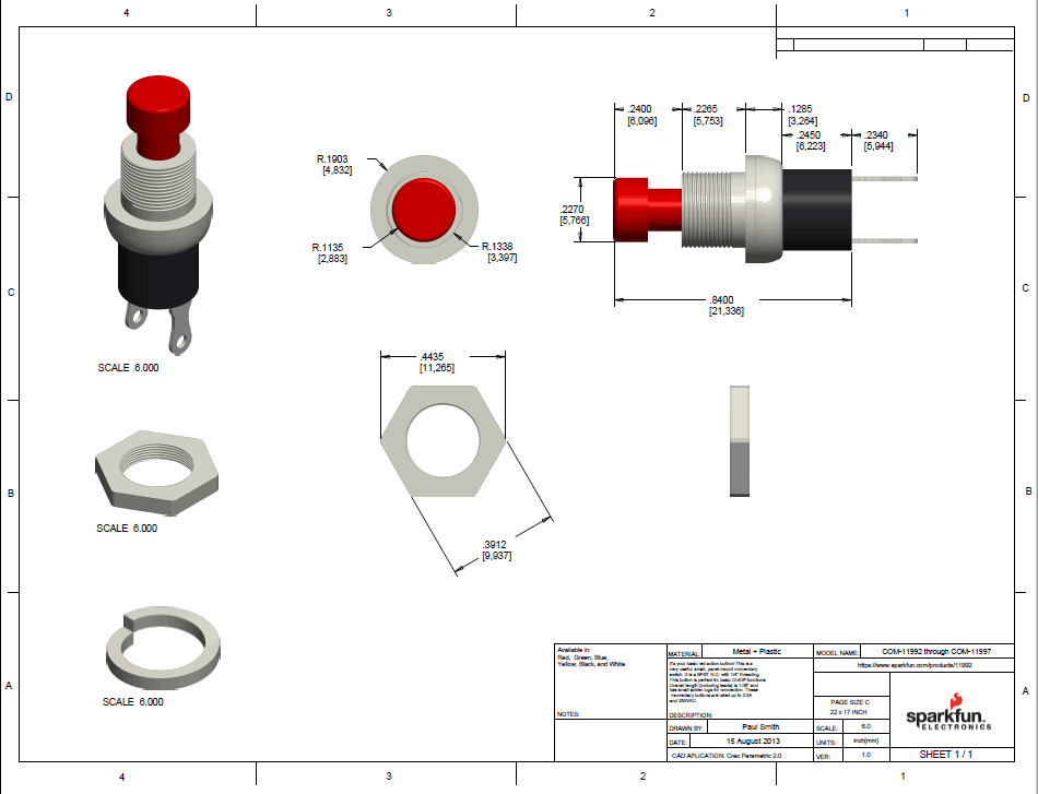
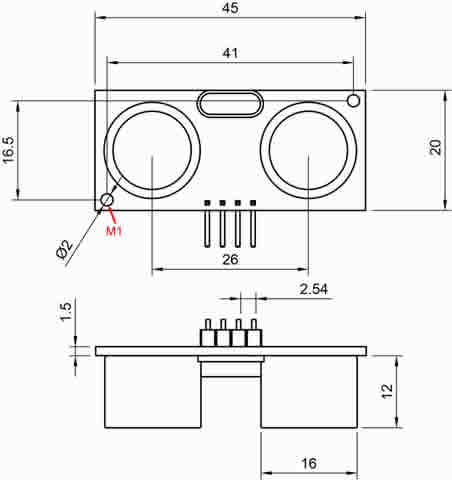
| The marriage of PCBs with 3D printed (thermoplastic) cases is facilitated through the use of heat-set insets as depicted in the image to the right. Our ACES program sources the M3×0.5 mm brass versions with an installed depth of 6.4 mm from McMaster-Carr. PCB designs should create mounting holes with a diameter of 3.2 mm to accommodate these insets. Click on the image to the right for a drawing. | ACES preferred fasteners are M3 nylon and we usually stock screws, nuts, and hex standoffs of various lengths. 3D thermoset printing (as is done with resin by JLCPCB) does not lend itself to the use of heat-set insets. ACES' preferred PCB/Case mounting alternative is to use nut pockets. | McMaster-Carr offers a wide variety of screws and fastenars of all sorts. Delivery is overnight. The DES maintains an inventory of M3 Nylon screws, with Phillips heads, in various lengths, between 5 mm and 20 mm. We typically have both off-white and black. | ACES preferred Power Barrel Jack is the Schurter 4840-2200 2.1 mm × 5 mm solderable version. It is a little larger than some but easier for ACES to hand tighten the collar. Since we use it on our 3D printed cases, insulation is not required. Click on the image below for design dimensions. | Panel mount devices such as momentary push buttons, toggle switches, and potentiometers come in a variety of dimensions. One such device is pictured below. This SPST NO Push Button is used as a reset switch in the ACES' Perma-Proto Kit. The key to its simple fastening within the resin-printed case is the nut pocket that permits simple thumb tightening. |
 |
 |
 |
 |
 |
Preparing Fusion 360 Design file (.f3d) for 3D Printing
TBD...
| Purpose: | To provide each student with an introduction to Computer-Assisted Drawing to explore design and production techniques as the natural and essential complement to his engineering skills. | 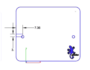 |
|---|---|---|
| Instructor: | Mr. Paul Elia | |
| Location: | DES | |
| Duration: | Six, 70-minute Sessions | |
| Software: | ViaCAD 2D3D Home Page ViaCAD 2D3D Power Pack (3D Printing Tools) |
The following video collection, prepared by Mr. Paul Elia, introduces you to some of the basic 2D CAD concepts and skills in ViaCAD 2D. (Vimeo)
 The ViaCAD 2D Desktop
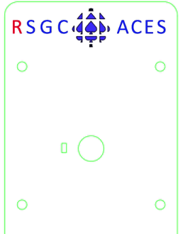 Resources