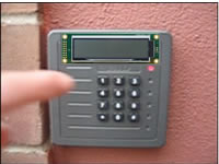
Entry
System.
In this multipart group project you will
develop
a
prototype of the deluxe version of the school's entry system
(shown to the right) by interfacing
a 12-Key
keypad with an ATmega16 and your Optrex
character LCD module.
Part
1. Interrupt On Any Key Pressed. TBD.
Part 2. Keypad Basics. Watch the Keypad 1 video. TBD.
Part 3. Single Pin Recognition and Display. TBD.
Part 4. 5-Pin Password Recognition, Display, and Confirmation (EEPROM).
TBD.
External
Interrupts: Photosensor.
Watch the video entitled Photosensor. In this project you will interface
a photomicrosensor with the ATmega16 to investigate the concept of an externally-generated
interrupt. Photomicrosensors
have many applications that include paper edge detection in printers
and copy machines. Their operation involves the light of an LED emitter
falling on an NPN Optotransistor. The device is considered ON as long
as the beam is detected. If the beam is blocked, the device is OFF. The model
you will be using is OMRON's EE-SX1081 (check
out a sample of a wide
variety of similar devices from OMRON or the EE-SX131).
LCD Experiment 3: Addressing. The standard Character LCD module
has enough DDRAM for 80 characters but typically even fewer displayable
positions. In 2-line mode (20 columns), this explains why the cursor
disappeared (along with a number of characters)
in the Entering
Text video.
With the support of your LCDdef.inc file, design and implement assembler
code that focuses on the Set
DDRAM instruction (0x80) to enable the direct addressing of DDRAM.
You are free to display any character pattern you wish, but
do so in a manner that confirms random (non-sequential) access to LCD
module's display locations.
Include purpose, media (photo & video link) and code sections
in your ER submission.
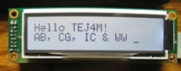
LCD Experiment 2: Entering Text. Now that you have a good sense
of how commands and data are uploaded to the LCD module manually, you are
ready to tackle the remaining Experiments outlined
in Part 1 of our LCD Guide as
programming projects.
Task. The Entering Text video to
the right displays the output requested by Experiment 2 on pp. 8-10 of
the LCD
Guide. Create a project called EnteringText and develop
fully documented assembler code to display the last 32 characters of the
character
table
defined on page 9. Detailed interfacing and programming instructions
can be found on pp. 30-46 in the DOT
MATRIX CHARACTER LCD MODULE USER�S MANUAL. Note: It is not
sufficient to simply have this project display the required output, rather,
your well-structured code will contain the following,
LCDdef.inc. Just as the include file m16def.inc holds equates
specific to the ATmega16 μC, you are asked to create a similar
file to hold equates for our specific LCD module. Download the include
file, LCDdef.inc to
the root folder of your AVR projects, and add equates for as many instructions
as are outlined in Table 3.1 List of Instructions on pp. 39-40 of the DOT
MATRIX CHARACTER LCD MODULE USER�S MANUAL. For this and all future
projects that use this LCD device, your code can include the assembler directive,
.INCLUDE "path\LCDdef.inc"
Program the data lines on PORTD and the control lines (RS, R/W, E) on PORTB.
Organizing your code into well-thought out subroutines will allow you to
create future programming projects quickly and reliably. For example, develop
subroutines to initialize the LCD unit, write a command, and write a data
byte.
Include procedure, character table graphic, photo and code sections in your ER submission.
LCD
Experiment 1: Basic Commands. The purpose of this assignment is to
gain familiarity with the basic interfacing principles of a modern character-based
LCD panel. You are asked to undertake the following steps.
Using the components
you have been provided with, prototype the development
circuit
as profiled
on
page 5 of this
primer complete with the debouncing circuit based on an SR
NAND FlipFlop. Keep in mind that the driver/control circuitry
is handled by an onboard chip. The industry standard for some time
has
been the Hitachi
HD44780, but the new batch of Optrex
C-51505 panels you are using
are based on Novatek's
NT3881D driver/controller architecture. This change requires one
change in the wiring of the prototype that you are asked to uncover
(Hint: examine the Timing Waveforms)
Next, undertake Experiment 1: Basic Commands and Experiment
2: Entering Text on
pp. 6-10 and call me over for a video when you're ready.
Prepare an comprehensive ER writeup of your investigations complete with
reasonably detailed tables, schematics, and explanations.
LED Cube 2. In version 2 of your LEDCube project, you are asked
to incorporate a Timer0 Interrupt strategy to assist in achieving
a 'Persistence
of View' (or PoV) in a new pattern of your own creative
design.
Your pattern should include distinct time intervals in which pairs or triples of
LEDs within different
levels and columns appear to be on simultaneously
as part of a pattern of esthetic appeal.
Note 1: You will be asked
to construct a standalone desktop model, so give your pattern some thought. Note 2: Could you figure out a way to offer more than one pattern
to users of your desktop model?
LED
Cube 1. RBK suggested the LED
Cube as an
appropriate starting point for this year's course. I agree as it gets us into
designing, building and simple testing right away. Review this PDF outline
for an idea of where we're headed. Search the web
under LED Cubes and study the various approaches that others have
employed.
Monday September 14
Using the supplied material (graph paper, plywood, drill and bits), create
the jig folder holding the LEDs for soldering.
Solder up each level, testing as you go.
Wednesday September 16, Monday September 21
Solder the three levels together
Test the assembly and make any necessary corrections.
Wednesday September 23
Final Manual Testing
Take photos and videos
Assembly language review
Friday September 25-Friday October 9
Over this period you will develop firmware that will light each of
the 27 LEDs in a sequence of your own design. Delays between LED lightings
should
be a multiple of 0.5 seconds. For your ER writeup entitled LED Cube
1: Delay Loop, please include the following sections,
Reference (include a link to the instructable)
Purpose (your words)
Procedure (your words)
Code (include a fully formatted and commented listing in Courier 9-10
point
Media (include a photo and link to video taken on Friday)
 Entry
System.
In this multipart group project you will
develop
a
prototype of the deluxe version of the school's entry system
(shown to the right) by interfacing
a
Entry
System.
In this multipart group project you will
develop
a
prototype of the deluxe version of the school's entry system
(shown to the right) by interfacing
a  External
Interrupts: Photosensor.
Watch the video entitled Photosensor. In this project you will interface
a photomicrosensor with the ATmega16 to investigate the concept of an externally-generated
interrupt. Photomicrosensors
have many applications that include paper edge detection in printers
and copy machines. Their operation involves the light of an LED emitter
falling on an NPN Optotransistor. The device is considered ON as long
as the beam is detected. If the beam is blocked, the device is OFF. The model
you will be using is OMRON's
External
Interrupts: Photosensor.
Watch the video entitled Photosensor. In this project you will interface
a photomicrosensor with the ATmega16 to investigate the concept of an externally-generated
interrupt. Photomicrosensors
have many applications that include paper edge detection in printers
and copy machines. Their operation involves the light of an LED emitter
falling on an NPN Optotransistor. The device is considered ON as long
as the beam is detected. If the beam is blocked, the device is OFF. The model
you will be using is OMRON's 
 LCD
Experiment 1: Basic Commands. The purpose of this assignment is to
gain familiarity with the basic interfacing principles of a modern character-based
LCD panel. You are asked to undertake the following steps.
LCD
Experiment 1: Basic Commands. The purpose of this assignment is to
gain familiarity with the basic interfacing principles of a modern character-based
LCD panel. You are asked to undertake the following steps.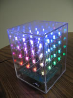 LED
Cube 1. RBK suggested the
LED
Cube 1. RBK suggested the 