 SIP Resistor Network. Circuits that wish to light individual LEDs singly, or in combination, are going to have to design appropriate resistance for each LED.
ACES: SIP Resistor Network |
SIP Resistor Network. Circuits that wish to light individual LEDs singly, or in combination, are going to have to design appropriate resistance for each LED.
The natural solution would be to place 10 separate resistors on the Cathode side of each LED in the bargraph. Voltage can be then applied on the respective Anode leads and each LED is protected. Simple, except that's a lot of fuss and the board looks messy despite how much care the designer takes.
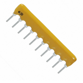
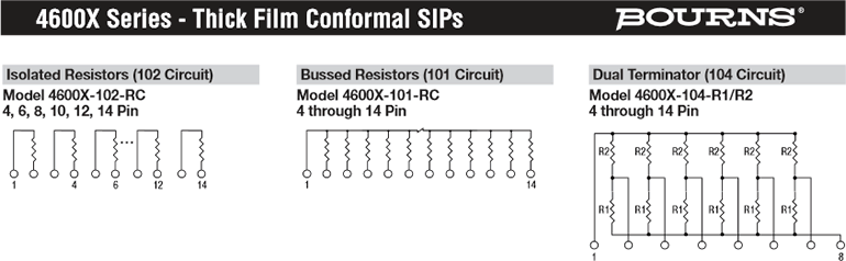
A cleaner, compact, and more efficient solution is to use a SIP (Single Inline Package) resistor network, an image of which appears to the right. These devices come in a number of design configurations: bussed, isolated, ladders, etc. We'll use the bussed design for our purposes.
Just as the LED bargraph has a bevel or notch as a reference marker, the resistor network has a dot to identify pin 1. Beside the dot you'll see identification markings. As we've become accustomed, a marking of 471 means 470 Ω (47×101). Pin 1 is the common pin. As can been determined from the image below, each lead is connected to pin 1 by the rated resistance.
Let's assume you had a SIP resistor network, some wire, an LED bargraph, and free some space on a breadboard.