 ACES prefer to make their own tools. During his time in the ACES program P. Bagga (ACES '17, U of T Eng. '22) developed his version of a breadboard-compatible power adapter. Affectionately dubbed the PB Machine, very slight variations to the design of the Printed Circuit Board (PCB) have been added by ACES since his graduation from our program.
Starting with the Fall 2022 session of ICS2O, Jr. ACES are asked to assemble their own device as a way of introducing them to the soldering equipment in the DES and this very important skill. Follow the instructions below to successfully assemble and test your RSGC ACES PB Machine.
 Please follow the instructions carefully and with caution as there are no replacement parts.
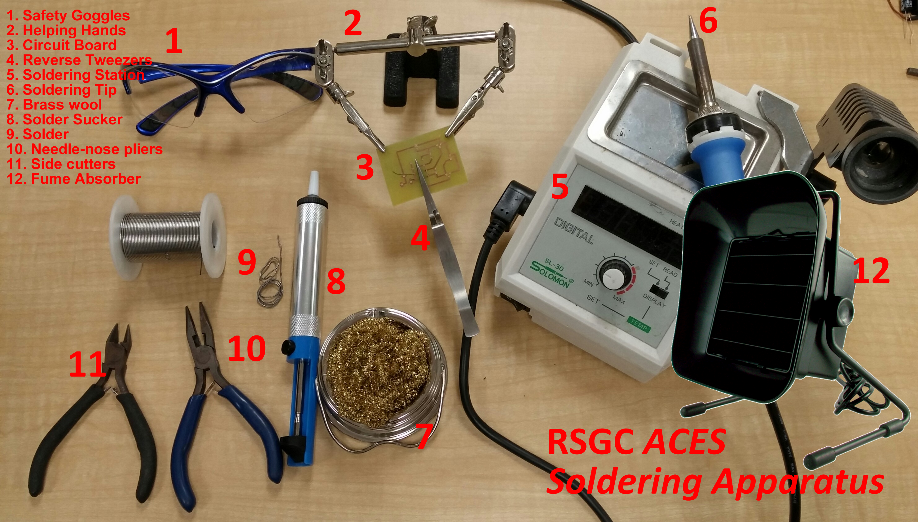
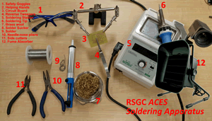 1. DES Workbench Soldering Stations. Multiple stations around the pperimter of the DES are made available for your prototype development efforts that incluide soldering components to generic or custom boards.
Soldering takes patience, skill, and a healthy respect for the characteristics of the tools. If you are unsure, seek assistance from the TAs or your teacher.
Click on the image to enlarge.
Wise ACES will watch this soldering video the N. Vassos (a former ACE) prepared for all of us to benefit from:
 Soldering Tips
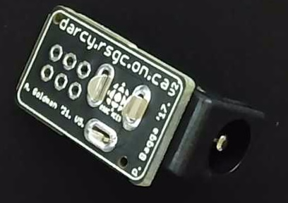
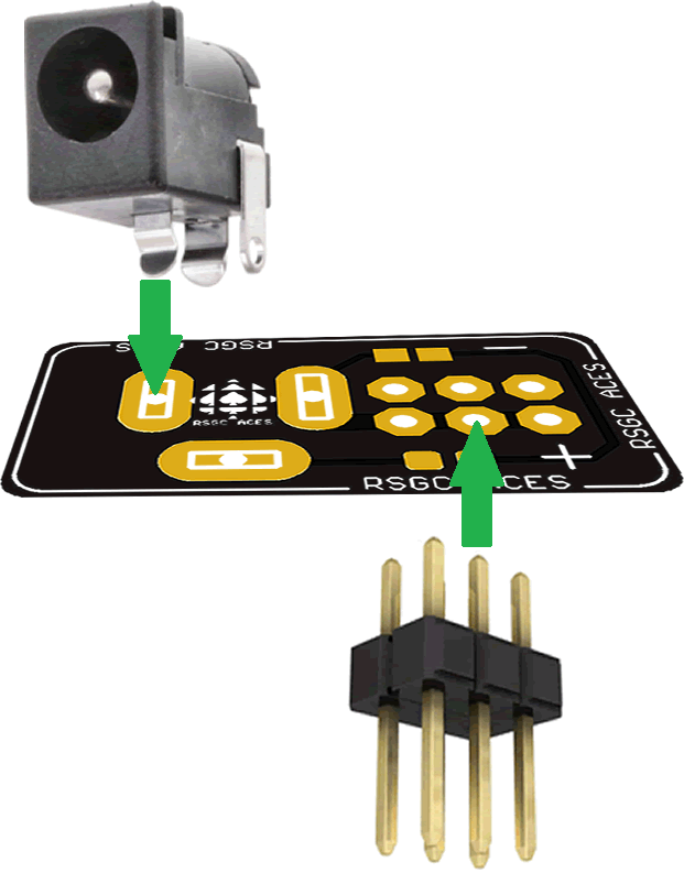
 2. PB Machine PCB. This small PCB has a number of features that make it an ideal interface between your power supply and your breadboard. Milled openings accept the kinked leads of the TOP-mounted 2×5.5 mm DC Power Jack. The onboard 1206 SMT LED and 10 KΩ resistor pair confirms the supply power is active. The 2×3 through-hole openings accommodate the BOTTOM-mounted male header pins. Silk screening is used to ensure the polarity (-/+) of the supply feed matches the power rail supplies. Click on the image to enlarge.
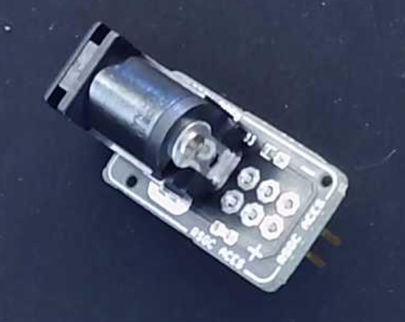
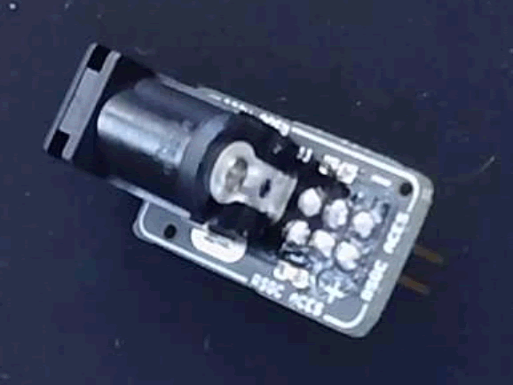
 3. DC Power Jack. Like many components, device characteristics vary. The most suitable power jack for the purposes of receiving the barrel from your battery snaps and 9V DC Wall Adapter is this one from CUI Devices. In addition to its 2.1 mm positive center post, the kinked leads provide strong support for soldering and operation when inserted into the PCB's milled openings.
Click on the before and after soldering images below to familiarize yourself with the insertion of the jack into the PCB.
At this stage you will insert your power supply into the jack to confirm the onboard blue LED lights up.
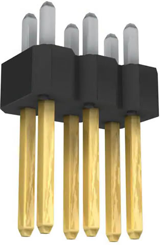 4. 6-Position (2×3) Male Header Pins. To this point, your device still has no means to provide power to your breadboard's supply rails. This is achieved in this final stage. The 6-position male header pins are inserted from the UNDER side of the PCB. Click on the images to enlarge.
This soldering is tricky for two reasons. The solder wire and tip of your soldering pen must hit each of the holes with the pins protruding through without resulting the solder briges that would create a short circuit.
Be sure to create a result in which the header pins are soldered perpendicular to the PCB for optimal use. Before inserting into your breadboard, insert your 9V supply to ensure the LED lights up as it did in the previous step. If it doesn't, disconnect your power supply before it gets hot as you have likely created a short. These are relatively easy to fix by removing solder that had inadvertently bridged the + and - post pins.