 LED Bargraph. Multiple LEDs bundled together into a single component is a useful device. Any metering device (voltage, volume, temperature, EMF, etc.) can use the number of LEDs lit to reflect the strength of the measurement or field.
 TEL3M ACES: LED Bargraph |
LED Bargraph. Multiple LEDs bundled together into a single component is a useful device. Any metering device (voltage, volume, temperature, EMF, etc.) can use the number of LEDs lit to reflect the strength of the measurement or field.
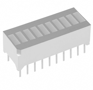
The typical package looks like the one to right. Ten square LEDs are encased in a single plastic block with the Anode (+) leads of each LED down one side and Cathode (-) leads down the other. One corner of the block has a bevel or notch to indicate the Anode side. Here's the rather simple internal circuit diagram,

LED bargraphs are readily available in red, green, and yellow.
The placement of the 20 leads lends itself well to straddling the valley down the middle of your breadboard.
CAUTION: Just like any LED you are used to, care must be taken to provide the correct voltage and current requirements for optimum performance. For example, green LEDs operate comfortably at 15 mA while drawing 2V. So, if you wish to test one of the LEDs in the device with a 9V DC power source, you'll have to drop 7V.
Let's assume you had one of these resistors, some wire, a green LED bargraph, and free some space on a breadboard.