
| RSGC ACES: introductory Nano Coding Tasks (first developed April 2024) |
13. Time. This project requires the onboard LED to turn on for a period of exactly 3 seconds whenever the button state changes from LOW to HIGH.
12. Pseudo-Random Number Generation (PRNG). TBD.
11. Iteration - for. Use your Arduino Template sketch to create a project entitled TempTable. Using what you have learned over the past few weeks, develop code that will yield a table of temperature equivalents that matches the table below.

10. PotPWM. The code found at File > Examples > Basic > Fade demonstrates the continuous use of the analogWrite() function to apply Pulse Wdith Modulation (PWM) to an LED on pin 9 as shown below. Create a new project PotPWM that will allow the user to manipulate the potentiometer from previous tasks to affect the brightness of the LED by performing an analogRead(A5) and scaling the 10-bit reading down to the 8-bit value required to perform an analogWrite() on pin 9, thereby controlling its brightness.

9. Map and Constrain. Orient 6 LEDs as shown below into pins D6 through D11. As can be seen in this orientation, to turn any LED on the digital pin must be grounded. Develop the project MapandConstrain, that will result in a type of VUMeter. As the user sweeps through the entire range of the potentiometer a single corresponding LED will be lit.

| LED | MIN | MAX |
|---|---|---|
| 6 | 0 | 171 |
| 7 | 172 | 343 |
| 8 | 344 | 515 |
| 9 | 516 | 687 |
| 10 | 688 | 859 |
| 11 | 860 | 1023 |
8. If...else Ladder. Orient 6 LEDs as shown below into pins D6 through D11. As can be seen in this orientation, to turn any LED on the digital pin must be grounded. Develop the project IFElseLadder, that will result in a type of VUMeter. As the user sweeps through the entire range of the potentiometer a single corresponding LED will be lit. The range for each LED is defined in the table to the right.
7.Temperature Conversion. Develop the sketch, Temperature, that will define a floating point value for a temperature in Celsius and convert it to Fahrenheit using the standard conversion formula. Provide suitable output to the Serial Monitor.
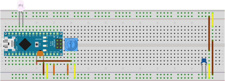
6. ADC. A potentiometer wired as a voltage divider yields an ANALOG voltage over the range defined by its two shoulder leads. In the diagram below, the brown wire presents this analog voltage on the A5 pin of the Nano.
You will recall in the earlier BicolorBlink task, the delay between alternations of red and green was fixed by the #define INTERVAL 1000 statement. Create the sketch, ADC, that will permit the user to control the frequency of alternation through the manipulation of the potentiometer. Add the 0.01 μF disk capacitor on A5 to filter out (reduce) noise.
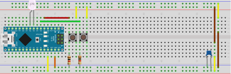
 5. Logic. Insert your bicolor LED into any two adjacent digital pins and retain two pull down PBs into any pair of digital pins. Develop the sketch. Logic, that will result in the green LED being lit if BOTH buttons are pressed, the red LED lit if ONLY one button is pressed, and OFF if neither is pressed.
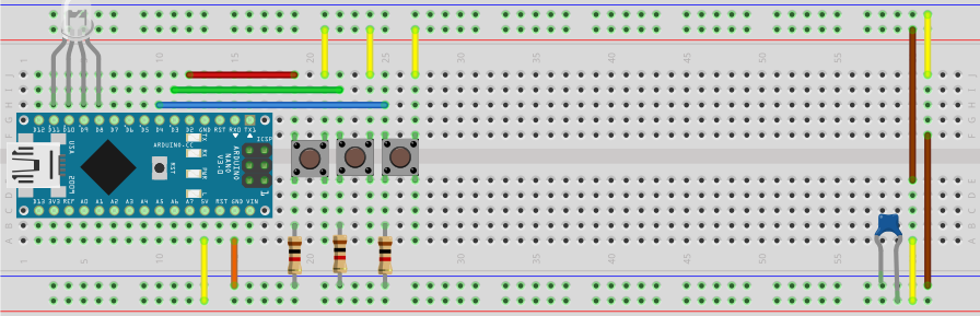
4. RGBLED. Insert the four leads of your CC RGB LED into any four adjacent digital pins. Wire a set of three pull down momentary PBs into any three digital pins. Develop the sketch RGBLED that maps each of the three PBs to each of the three LED anode leads so that uses can select either red, green, blue or any combination thereof.
3. ButtonLEDIO. Wire a pull down momentary push button to present its signal into D2 (shown below). Develop the sketch ButtonLEDIO to echo the state of the button onto the onboard Nano LED.
2. BicolorBlink. Insert the leads of your Bicolor LED into a pair of adjacent digital pins. Develop the sketch BicolorBlink that will result in alternate red and green flashing.
1. Blink. Confirm the File>Examples>Basics>Blink sketch. Improve it in any way you can.