Once your prototype is working and you've gathered media confirming as much (and revealing the quality of your build), you are ready to assemble the permanent version. Your supplemental parts kit contains the new and replacement parts, with the exception of the four fixed resistors which you can provide from your own inventory.
Parts
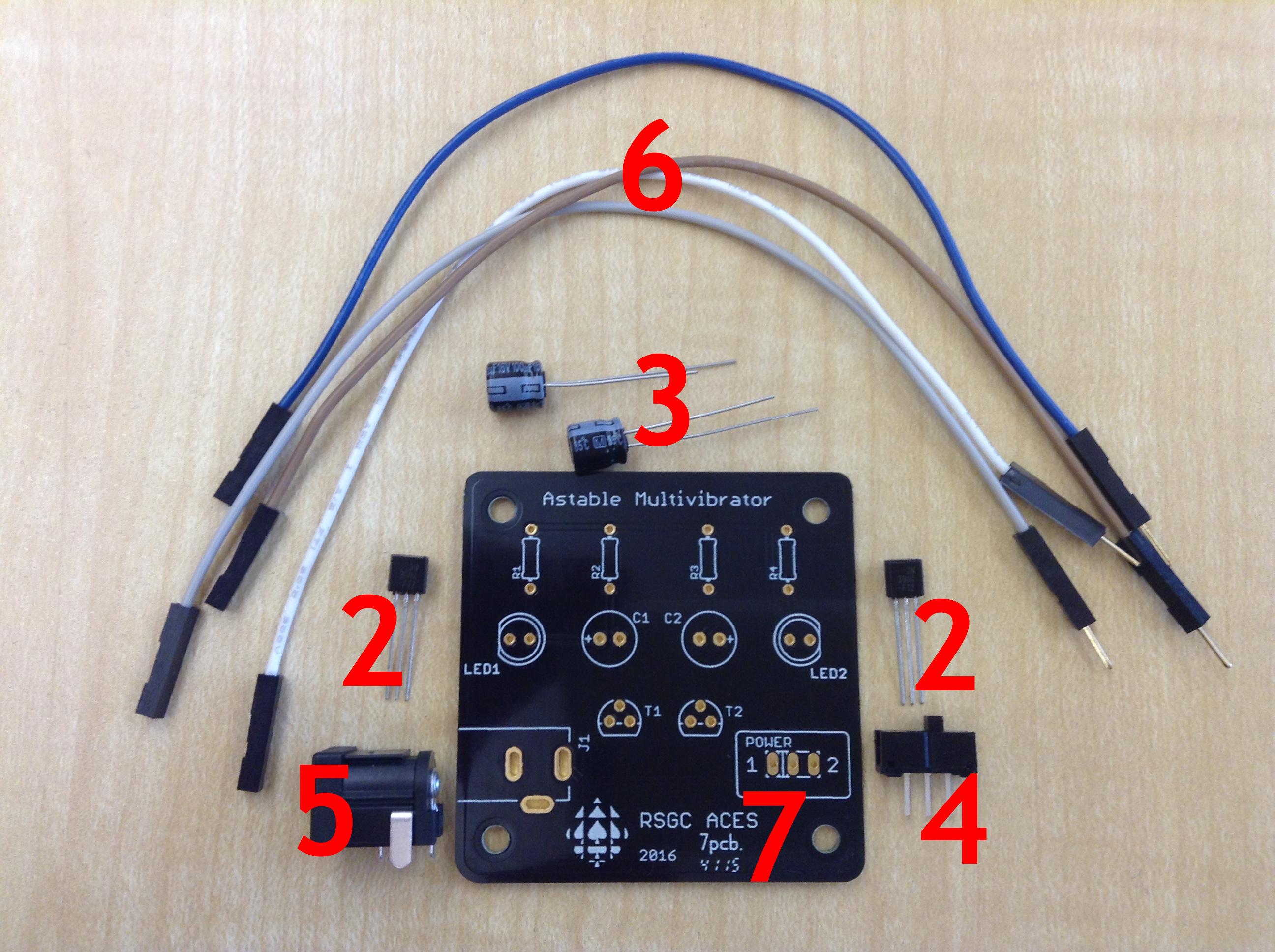
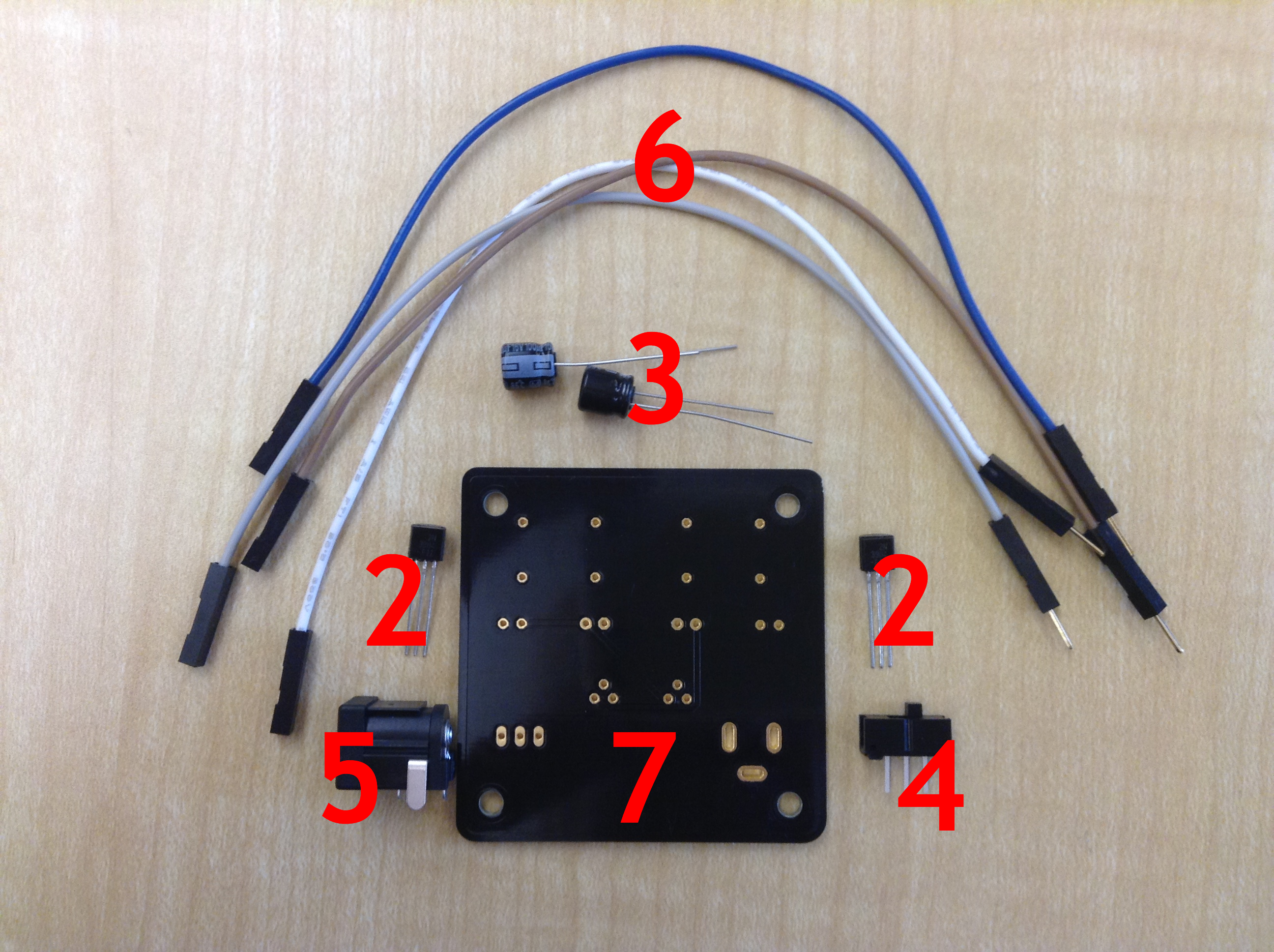
The parts are numbered below in the exact order they should be soldered to your Printed Circuit Board (#7). The order is simply the smallest profile items to the largest. Tips. The PCBS are fragile. Paying attention to the silk screening on the PCB will ensure you insert the components with the correct polarity. Be sure your tip remains clean at all times by regularly dipping it into the brass wool. Remember, you have 3s-4s to solder a lead, otherwise damage to the part is likely to occur.
- Fixed Resistors (not shown). Solder these first, bending the leads so the part stays tight to the PCB. Use the reverse tweezers to maintain their tight contact with the PCB.
- 2N3904 NPN Transistors. Gently push the transistors down just until they provide a little resistance due to the spreading of their leads, no further. Note: Transistors are particularly vulnerable to excessive heat, even through accumulation. It is recommended that one lead of the first transistor is soldered, then a lead from the second transistor, then back to the first transistor, and so on...
- 100μF16V Electrolytic Capacitors. Watch the polarity and, again, 3s-4s, no more!
- On/Off Slide Switch. Tough to get this step wrong but make sure the switch remains tight to the board during the soldering process.
- DC Jack. Similar to the slide switch, the pads define its position and make sure the past is remains tight to the board.
- 6" Jumper Wires. Solder the male ends of the four jumper wires to the pads, ensuring they're inserted as far as possible. The extra length is meant to ensure the LEDs reach to your pumpkin's eyes.
- Printed Circuit Board. The PCB is made of fibreboard with interconnected copper traces joining copper pads. Excessive heat can cause the copper pads to separate from the fibreboard rendering the PCB virtually useless. Be careful and think!
Good luck!