Check out this Arduino-based Radar Project; it's one of many out there (here's his LCD version). To be fair it's actually a SONAR project (SOund Navigation And Ranging) as RADAR is an acronym for RAdio Detection And Ranging. The author generously provides high-level source code for both the Arduino and the Processing Visualization.
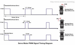
Apart from the wow factor of the exercise, Sr. ACES are drawn to it because both the HC-SR04 distance sensor, and the servo it is mounted on, are PWM-based devices. This provide a perfect opportunity to fine-tune our low-level AVR Assembly timer skills.
 The statements: myServo.write(i);, delayMicroseconds(10);, and duration = pulseIn(echoPin, HIGH); are high-level abstractions of low-level, timer-based configurations, that need to be explored.
Task.
- You are to create a physical (2D/3D) environment consisting of objects in random, relocatable, positions.
- Using (at least) one HC-SR04 distance sensor, mounted to a servo, you are to scan your environment over a range of at least 120ˆ continuously capturing position data and presenting a dynamic graphic model of the data. You have a servo. I will distribute an HC-SR04 sensor, a 4-pin M/F cable and a mount on Tuesday. Alternatively, you can acquire a different servo and/or mount.
- The software to capture the data is to be written entirely in AVR assembly.
- Your assembly code for both the servo and the HC-SR04 will make maximum, effiicient use of the AVR's Timer Modes, Registers, Flags and Interrupts.
- The code for the visualization of the environment can be written in the language of your choice.
- You can choose the hardware vehicle (and software) for the visualization.
Parts Kit
- In addition to the HXT500 servo motor you have in your kit (feel free to acquire a different one if you wish) your group has been provided with an HC-SR04 rangefinding sensor, servo motor mount (again, feel free to come up with a different solution), and a 4-pin Male/Female cable for your sensor.
Project Format
 This project as well as the order of presentation will be undertaken in groups as follows: RM/SA/ST, CNC/GC, MK/MM, JG/TD, AE/PB, MB/BL. Feel free to divide the labour within your group as you see fit.
- Each group will present their project to the class on Friday March 10. If your parents are dragging you away early for the March Break, your group will present on Wednesday March 8.
- Your ER summary is due the following day, Saturday March 11. You may have common media but the text is to be entirely unique to each group member.
Reference, Research, Read and Read Some More (in order)
- ATmega328P Full Datasheet: Timer 1. Input Capture Unit. Section 16.6, pp. 117-119.
- Atmel's Application Notes (AVR135) Using Timer Capture to Measure PWM Duty Cycle on tinyAVR and megaAVR devices (support files for AVR135: device.h, icp.h, icp.c, main.c)
- Datasheet: Hextronik HXT900
- Datasheet: HC-SR04
- Lots of blogs and videos out there (for high-level implementations) What you're required to do likely doesn't exist; that's the 'A' in ACES :)
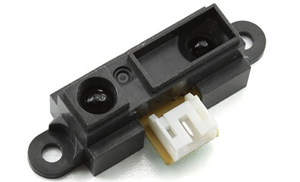
The Sharp IR distance sensor we used earlier in the year used an infrared signal to detect its distance from an object.
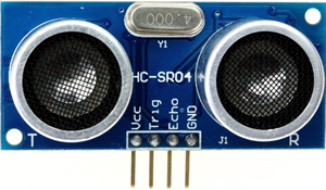
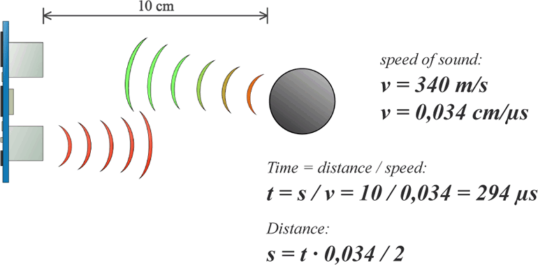
The HC-SR04 Ultrasonic distance sensor exploits a 4kHz sound signal to approximate its distance from an object.
 Check out this Arduino-based Radar Project; it's one of many out there (here's his LCD version). To be fair it's actually a SONAR project (SOund Navigation And Ranging) as RADAR is an acronym for RAdio Detection And Ranging. The author generously provides high-level source code for both the Arduino and the Processing Visualization.