| 2009-2010 TEI4M Engineering Interfacing Tasks |
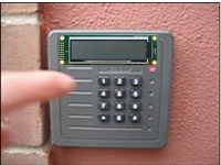
Deluxe Entry Panel. In this 5-part group project you will develop a remote prototype of the deluxe version of the school's entry panel by interfacing the ATmega16 with the 12-Key telephone keypad and your Optrex character LCD module.
PART 2. External Interrupt On Keypress.
PART 3. Single Key Recognition.
PART 4. 5-Key Password Recognition.
PART 1. How a Keypad Works. Complete the following tasks.
- Watch the Entry 1 video
- With your DMM set to Continuity, confirm the connection data presented in the chart below and/or this reference page.
- Using the LED bargraphs (with resistor network!), develop a prototype identical to the one presented in video to confirm the connections
- Obtain media and prepare an ER submission
 PART 2. External Interrupt On Keypress. Complete
the following tasks.
PART 2. External Interrupt On Keypress. Complete
the following tasks.
- Watch the Entry 2 video
- (Reference) Read Chapter 4, Interrupt Subsystem (pp. 65-71)
- (Reference) ATMEL's Application Note for the 4x4 Keypad Wakeup on Keypress
- Create the AVRStudio Project Entry2, add the code provided on pp. 10-13 of the Application Note, and adapt the ISR to flash the text, Keypressed to the LCD for 1 second, prior to returning to the Ready state.
- Implement the prototype depicted in the video
- Obtain media and prepare an ER submission
- Check out the future replacement for the Keypad
 PART 3. Single Key Recognition. Complete
the following tasks.
PART 3. Single Key Recognition. Complete
the following tasks.
- Watch the Entry 3 video
- Read over the ATMEL Appnote entitled: AVR240: 4 x 4 Keypad - Wake-up on Keypress
- Connect the Keypad as suggested and blend their code suggestions with your EP2 code to determine the key pressed and echo the corresponding character stored from EEPROM to your LCD Screen
- Obtain media and prepare an ER submission that includes Purpose, Procedure and Media
PART 4. 5-Key Password Recognition. The ATmega16 has 1K of SRAM. The 32 General Purpose registers (R0 through R31) and 64 dedicated Ports consume the first 96 (0x60) bytes, after which your code is free to use the contents for data storage. This final stage of your Entry Panel Project will accept 5 characters followed by the # sign and store them in SRAM. Once the # sign is entered, your code will attmept to determine a match with the correct password previously stored in EEPROM. The result of the comparison will result in an appropriate message displayed to the LCD. A bicolor LED is to be added to reflect the outcome of the password entry. Complete the following tasks.
- Watch the Entry 4 video
- Review this tutorial on SRAM storage and retrieval. Review the ATmega16's Data Transfer Instructions found on page 13 of the Instruction Set Manual.
- Start a new AVR Project and copy the code from EP3.
- Adapt the code for this Stage.
- Obtain media and prepare an ER submission
 PART
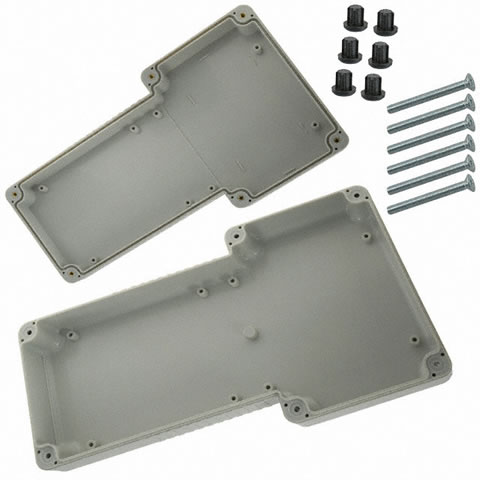
5. Hand-Held Prototype. In this culminating segment, you are
to refresh your mechanical skills and assemble a remote hand-held prototype
of your LCD Entry Panel. Documenting as you go (photos/videos),
you are to complete the following tasks,
PART
5. Hand-Held Prototype. In this culminating segment, you are
to refresh your mechanical skills and assemble a remote hand-held prototype
of your LCD Entry Panel. Documenting as you go (photos/videos),
you are to complete the following tasks,
- Develop a standalone prototype of your LCD/EP on a breadboard to ensure your circuit works independently of the STK500. Be careful to ensure all power requirements (voltage & amperage) are satisfied.
- Taking careful measurements (you can use the digital calipers), familiarize yourself with the specifications of the T-Case, paying particular attention to the placement and mounting options of the PCB, keypad and LCD screen you will need to house. Transfer these measurements to the copper-clad board(s).
- Using EAGLE, lay out the circuit board
- Create the PCB
- Mount and test
- Prepare your final ER submission
 External
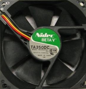
Interrupts: Tachometry. The specifications
of the TA350DC fan (Model: M34422-23) state their fan
is capable of 3500 rpm or roughly 57 rps. In this assignment
you are asked to confirm their claim. The
Yellow wire of the 3-wire DC fan you
have been given (Red=Positive, Black=Negative)
reports a tach signal on each rotation. Capitalizing
on your expertise with external and timer interrupts, you have to abilty
to monitor this rotation and dynamically report the results to your LCD.
External
Interrupts: Tachometry. The specifications
of the TA350DC fan (Model: M34422-23) state their fan
is capable of 3500 rpm or roughly 57 rps. In this assignment
you are asked to confirm their claim. The
Yellow wire of the 3-wire DC fan you
have been given (Red=Positive, Black=Negative)
reports a tach signal on each rotation. Capitalizing
on your expertise with external and timer interrupts, you have to abilty
to monitor this rotation and dynamically report the results to your LCD.
As you recall, the ATmega16's Timer Interrupt Systems can be configured in a variety of ways. In the previous sensor assignment, you counted the number of overflows of the full 8-bit TCNT0 register. You manually controlled the interval of time over which the overflow interrupts were counted through your interaction with the sensor. In this assignment you need the microcontroller to define a precise 1s interval over which the count of the external interrupts are recorded, prior to presentation.
Task. Construct a monitoring system that meets the power input requirements defined by the datasheet and dynamically reports the rotation rate of the fan. Use your LCD programming skills to provide a well-formatted dynamic display.
Obtain a photo and video on Thursday March 4 to be used in support of an ER summary that also includes the Tachometry.asm code listing.
 [VIDEO] External
Interrupts: Photomicrosensor.
[VIDEO2] In this project you will interface
a photomicrosensor with the ATmega16 to extend your investigation of
externally-generated interrupts. Watch the video entitled Photosensor.
Photomicrosensors have many applications that include paper edge detection in
printers
and copy machines. Their operation involves the light of an LED emitter
falling on an NPN Optotransistor. The device is considered ON as long
as the beam is detected. If the beam is blocked, the device is OFF. The model
you will be using is OMRON's EE-SX1081 (check
out a sample of a wide
variety of similar devices from OMRON).
[VIDEO] External
Interrupts: Photomicrosensor.
[VIDEO2] In this project you will interface
a photomicrosensor with the ATmega16 to extend your investigation of
externally-generated interrupts. Watch the video entitled Photosensor.
Photomicrosensors have many applications that include paper edge detection in
printers
and copy machines. Their operation involves the light of an LED emitter
falling on an NPN Optotransistor. The device is considered ON as long
as the beam is detected. If the beam is blocked, the device is OFF. The model
you will be using is OMRON's EE-SX1081 (check
out a sample of a wide
variety of similar devices from OMRON).
 Task. You
are going to turn this assignment into a test of your temporal cognition. When
the sensor is first tripped, the ATmega16's counter will start. When
the sensor is tripped a second time, the counter will stop and the elapsed
time will be displayed on the LCD. The
challenge
will
be
to time your interrupts as close to 1 second as possible. This project will
be organized into three stages.
Task. You
are going to turn this assignment into a test of your temporal cognition. When
the sensor is first tripped, the ATmega16's counter will start. When
the sensor is tripped a second time, the counter will stop and the elapsed
time will be displayed on the LCD. The
challenge
will
be
to time your interrupts as close to 1 second as possible. This project will
be organized into three stages.
Stage 1. External Interrupt 0. You must get the External Interrupt on PD2 to respond to the microsensor. This will be confirmed by an announcement on your LCD panel.
Stage 2. Toggle Interrupt Sense Control. Modify Stage 1 so that on the first interrupt (triggered by a rising edge), the ISR reverses the sense control (ISC01/ISC00) to prepare for detection of the falling edge. To accomplish this, you should maintain a variable (register) that you toggle back and forth. The com instruction works well for this. (Note: Make sure you use a register that is not in use elsewhere (like the Delay routine), because this can slow your progess down significantly (trust me on this point). Your LCD should report something like ON/OFF. The action you're looking for is that when the beam is broken it says ON, and when the obstruction is removed it reports OFF.
Stage 3. Timer/Counter0 Overflow Interrupt. You are going to tap into the mega16's system clock to record the number of clock signals between the interrupts in Stage 2, with the goal of having the LCD report an interval as close to 1 second as possible. From the discussion in class, configure the microcontroller clock for 1MHz, Timer/Counter0 prescaled for clk64, and enable the Timer/Counter0 overflow (normal mode). Your overflow service routine should simply count the number of times TCNT0 overflows. On the second External Interrupt, report the count to the LCD. Question: Given this configuration, what count value would you expect to see for an interval of exactly 1 second?
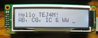
[VIDEO] External Interrupts: Int0 & Int1 (Counting). In your groups (CG&IC, AB&WW), implement the external interrupt experiment described on page 4 of this tutorial, adapted for the ATmega16. Call for a photo and video when completed and include these in your submission.
 LCD
Experiment 6:
Binary⇔ASCII Conversion.
Since many of the upcoming practical applications are data-generating projects
that require numeric results to be displayed on your LCD screen, this
last LCD
experiment will develop the necessary code that converts the binary
contents of a two-byte register pair to ASCII. The typical solution involves
a two-step procedure in which the binary value is first converted to BCD
(binary coded decimal) that we examined last year
(Digital Design, p. 18). From BCD, it is a simple matter of adding 0x30 to
the digit value to achieve
the ASCII equivalent. The two online resources for the binary to BCD algorithm
can be found in ATMEL's
Application Notes (AVR204) and this
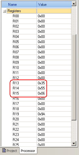
independent site, both of which we'll review in class. The screen capture
to the right reflects the state fo the registers at the end the routine suggested
by the ATMEL Application Note. A rollover of the image reveals the state of
the registers (ASCII) left by the code from the independent site.
LCD
Experiment 6:
Binary⇔ASCII Conversion.
Since many of the upcoming practical applications are data-generating projects
that require numeric results to be displayed on your LCD screen, this
last LCD
experiment will develop the necessary code that converts the binary
contents of a two-byte register pair to ASCII. The typical solution involves
a two-step procedure in which the binary value is first converted to BCD
(binary coded decimal) that we examined last year
(Digital Design, p. 18). From BCD, it is a simple matter of adding 0x30 to
the digit value to achieve
the ASCII equivalent. The two online resources for the binary to BCD algorithm
can be found in ATMEL's
Application Notes (AVR204) and this
independent site, both of which we'll review in class. The screen capture
to the right reflects the state fo the registers at the end the routine suggested
by the ATMEL Application Note. A rollover of the image reveals the state of
the registers (ASCII) left by the code from the independent site.
Task.
- Create an ATmega16 project entitled Binary2ASCII.
- To the source code, add the equate .equ data=65535
- Using the strategy of your choice, implement the code to load registers with the BCD equivalent of the value stored in data
- Document your code and submit it to handin by the first deadline
- Convert the BCD representation to ASCII and display the value on your LCD module and submit an ER writeup by the second deadline.
 LCD
Experiment 5: Character Entry Mode. Read Experiment
5: Character Entry Mode described on page 13. I've prepared an
animated gif of the action of the calculator described in the
reading. Your task is to duplicate this behaviour on your LCD module. The
goal is to simulate the manual entry of a value while leaving the impression
that the cursor is standing still. Use the code below to define the value
that could be displayed.
LCD
Experiment 5: Character Entry Mode. Read Experiment
5: Character Entry Mode described on page 13. I've prepared an
animated gif of the action of the calculator described in the
reading. Your task is to duplicate this behaviour on your LCD module. The
goal is to simulate the manual entry of a value while leaving the impression
that the cursor is standing still. Use the code below to define the value
that could be displayed.
   Entry:
     .db	"3.141592"
   EntryEnd:
[VIDEO] LCD Experiment 4: Shifting. Read Experiment 4: Shifting the Display described on page 12 and then watch the Shifting video above. Create a project called Shifting and drop in Shifting.asm found here. Add the LCDDef.inc file to the project available from the same location.
Review the code, program your ATmega16, observe the results, and consider the implications.
You are not required to submit this project.
[VIDEO] LCD Experiment 3: Addressing. The standard Character LCD module has enough DDRAM for 80 characters but typically even fewer displayable positions. In 2-line mode (20 columns), this explains why the cursor disappeared (along with a number of characters) in the Entering Text video.
Task.
- Read Experiment 3: Addressing in Part 1 of our LCD Guide starting at the bottom of page 10.
- View the Addressing video.
- With the support of your LCDdef.inc file, design and implement assembler code that focuses on the Set DDRAM instruction (0x80) to enable the direct addressing of DDRAM. You are free to display any character pattern you wish, but do so in a manner that confirms random (non-sequential) access to LCD module's display locations.
Include purpose, media (photo & video link) and code sections in your ER submission.
[VIDEO] LCD Experiment 2: Entering Text. Now that you have a good sense of how commands and data are uploaded to the LCD module manually, you are ready to tackle the remaining Experiments outlined in Part 1 of our LCD Guide as programming projects.
Task. The Entering Text video to the right displays the output requested by Experiment 2 on pp. 8-10 of the LCD Guide. Create a project called EnteringText and develop fully documented assembler code to display the last 32 characters of the character table defined on page 9. Detailed interfacing and programming instructions can be found on pp. 30-46 in the DOT MATRIX CHARACTER LCD MODULE USER�S MANUAL. Note: It is not sufficient to simply have this project display the required output, rather, your well-structured code will contain the following,
- LCDdef.inc. Just as the include file m16def.inc holds equates
specific to the ATmega16 μC, you are asked to create a similar
file to hold equates for our specific LCD module. Download the include
file, LCDdef.inc to
the root folder of your AVR projects, and add equates for as many instructions
as are outlined in Table 3.1 List of Instructions on pp. 39-40 of the DOT
MATRIX CHARACTER LCD MODULE USER�S MANUAL. For this and all future
projects that use this LCD device, your code can include the assembler directive,
.INCLUDE "path\LCDdef.inc"
- Program the data lines on PORTD and the control lines (RS, R/W, E) on PORTB.
- Organizing your code into well-thought out subroutines will allow you to create future programming projects quickly and reliably. For example, develop subroutines to initialize the LCD unit, write a command, and write a data byte.
- Program in the required delays as found within the 8-bit Initialization Flowchart on page 32 and the Execution Time column of Table 3.1 List of Instructions on page 39.
 LCD
Experiment 1: Basic Commands. The purpose of this assignment is to
gain familiarity with the basic interfacing principles of a modern character-based
LCD panel. You are asked to undertake the following steps.
LCD
Experiment 1: Basic Commands. The purpose of this assignment is to
gain familiarity with the basic interfacing principles of a modern character-based
LCD panel. You are asked to undertake the following steps.
- Using the components you have been provided with, prototype the development circuit as profiled on page 5 of this primer complete with the debouncing circuit based on an SR NAND FlipFlop. Keep in mind that the driver/control circuitry is handled by an onboard chip. The industry standard for some time has been the Hitachi HD44780, but the new batch of Optrex C-51505 panels you are using are based on Novatek's NT3881D driver/controller architecture. This change requires one change in the wiring of the prototype that you are asked to uncover (Hint: examine the Timing Waveforms)
- Next, undertake Experiment 1: Basic Commands and Experiment 2: Entering Text on pp. 6-10 and call me over for a video when you're ready.
- Prepare an comprehensive ER writeup of your investigations complete with reasonably detailed tables, schematics, and explanations.
LED Cube 2. In version 2 of your LEDCube project, you are asked to incorporate a Timer0 Interrupt strategy to assist in achieving a 'Persistence of View' (or PoV) in a new pattern of your own creative design.
Your pattern should include distinct time intervals in which pairs or triples of LEDs within different levels and columns appear to be on simultaneously as part of a pattern of esthetic appeal.
Note 1: You will be asked
to construct a standalone desktop model, so give your pattern some thought.
Note 2: Could you figure out a way to offer more than one pattern
to users of your desktop model?
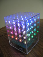 LED
Cube 1. RBK suggested the LED
Cube as an
appropriate starting point for this year's course. I agree as it gets us into
designing, building and simple testing right away. Review this PDF outline
for an idea of where we're headed. Search the web
under LED Cubes and study the various approaches that others have
employed.
LED
Cube 1. RBK suggested the LED
Cube as an
appropriate starting point for this year's course. I agree as it gets us into
designing, building and simple testing right away. Review this PDF outline
for an idea of where we're headed. Search the web
under LED Cubes and study the various approaches that others have
employed.
- Using the supplied material (graph paper, plywood, drill and bits), create the jig folder holding the LEDs for soldering.
- Solder up each level, testing as you go.
- Solder the three levels together
- Test the assembly and make any necessary corrections.
- Final Manual Testing
- Take photos and videos
- Assembly language review
Friday September 25-Friday October 9
Over this period you will develop firmware that will light each of the 27 LEDs in a sequence of your own design. Delays between LED lightings should be a multiple of 0.5 seconds. For your ER writeup entitled LED Cube 1: Delay Loop, please include the following sections,
- Reference (include a link to the instructable)
- Purpose (your words)
- Procedure (your words)
- Code (include a fully formatted and commented listing in Courier 9-10 point
- Media (include a photo and link to video taken on Friday)