4. DS1307 Square Wave Exploration
 In this exercise you'll gain familiarity with both the Arduino Serial Plotter and the DS1307's Square Wave functionality. We'll also review external interrupts.
Reference 1:  Arduino Serial Plotter: Multiple Graphs
Reference 2: Arduino DS1307 Real Time Clock Square Wave Generator
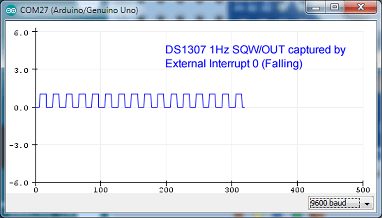
The Serial Plotter feature is crude but can be inspiring to visualize your data. You simply use the Serial print and println functions for numeric data and launch the Serial Plotter feature in the Tools menu. Changing the baud rate can adjust the speed of animation of your plot.
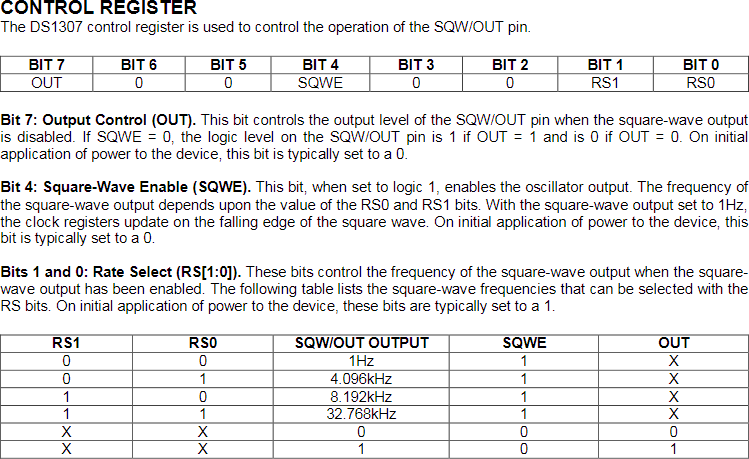
Our goal will be to plot various square waves generated through Wire-level manipulation of Register 7 in the DS1307 and combining the output with our knowledge of external interrupts and register-level coding techniques.
As can be determined below left, one pin on the DS1307 (pin 7) offers an open drain square wave signal that mimics the oscillation of the crystal (32.768 kHz). Through the setting of internal prescalers, the signal can be divided down to achieve three other frequencies,
(8.192 kHz, 4.096 kHz or 1 Hz). The block diagram (below, left) shows the required use of an external pullup resistor in combination with the open drain pin. However, since we're using a microcontroller, setting the internal pullup resistor on the input pin for this signal, simplifies the circuit further.
Stage 1. Enable the RTC Square Wave.
- Create the sketch RTCSquareWavePlotter.
- Using Wire-level commands only, configure the RTC's Register 7 to enable the Square Wave with a frequency of 1 Hz.
Stage 2. RTC Square Wave Interrupt
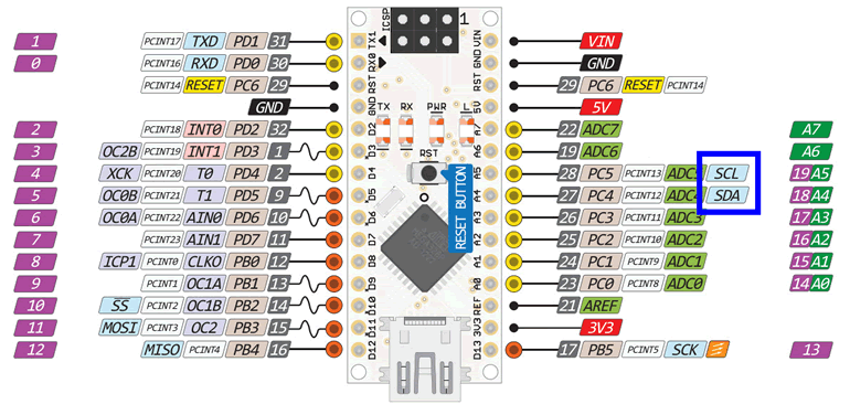
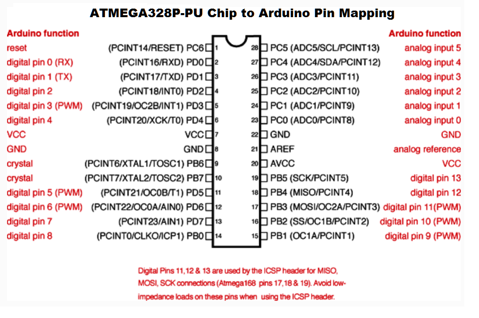
- The goal of the second stage is to configure our RTC's Square Wave to interrupt our code with a known frequency so that we may have our sensor(s) take its reading and its data logged to EEPROM. The ATmega328P offers two external interrupt pins (INT0 and INT1) mapped to Arduino pins 2 and 3, respectively. Since INT1 (pin 3) is also mapped to a PWM source, we'll avoid that one, in case we require it later. Wire your RTC's SQW pin to Arduino pin 2.
- As the SQW pin is an open-drain type we need to attach a pullup resistor. Configure the appropriate GPIO register to set the pullup resistor on pin 2 (using register-level code if possible).
- Within the setup() function, attach an interrupt function,
ISR_pulse(), to Arduino pin 2, to be invoked on a FALLING event .
- Implement the function
ISR_pulse() as an Interrupt Service Routine (ISR) so that will increment the global variable volatile count,
- (OPTIONAL) Set the global variable volatile triggered to true, and toggle the state of pin 13, every time the pin senses a CHANGE event. Have your loop() function check the value of triggered. On true, set triggered to false, and use Wire-level calls to obtain the RTC's time and date information and println the values to the Serial Monitor.
Stage 3. Plotting the Square Wave
- Comment out all existing
Serial.print and println calls.
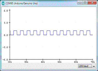
- Add the statement Serial.println(count%2) to your loop() function, to be executed on every iteration (not just when triggered)
- Run your code and launch the Serial Plotter instead of the Serial Monitor.
- Reduce the baud rate to 1200 in both your
setup() function and the Serial Plotter to slow the display down.
3. DS1307 RTC Timekeeping Registers
Reference 1: Wire Library
Reference 2: DS1307 Datasheet
Reference 3: DS1307 Registers
 Watch this 30s video to see what we're going after using the
 Wire Library only: DateTime- Assemble the hardware platform pictured to the right (with the quick connect RTC Breakout board and the LCD as an appliance if you can)
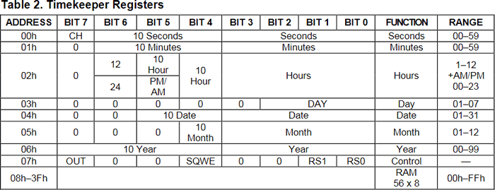
- Open the DS1307 RTC datasheet to the CLOCK AND CALENDAR discussion on page 8. Review and digest as much as you can. A capture of the DS1307's Register structure appears above.
- Create a new project sketch, WireLevelRTCLCD and drop in this code shell.
- Complete the DS1307 #define compiler directive for its specific I2C address.
- Note the use of a
struct data type to tightly bind together multiple data fields relating to a single time instant.
- Review the
setup(), and loop() functions.
- C's printf() function (and String variant, sprintf() ) facilitate readable output. Review their use.
- The
void getAll(timeDate &td) function introduces you to an efficient technique for functions to pass back multiple data values
- Utility functions are required to provide compatibility between registers and display devices. Develop the bodies of these two conversion functions in the form of single expressions.
uint8_t BCD2bin(uint8_t bcd)
And, as is usually the case, you'll need the complementary function,
uint8_t bin2BCD(uint8_t bin)
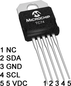 2. TC74 Tiny Serial Digital Thermal Sensor
Reference 1: RSGC ACES Workbook: AVR Foundations, p. 93.
Reference 2: Wire Library, Explored
Reference 3: TC74 Tiny Serial Digital Thermal Sensor Datasheet
- Review AVR Foundations, p. 93. in particular, the (few) registers that are accessible.
- Open the TC74 Datasheet and go to Section 4.0, The Register Set and Programmer's Model, on page 8.
- From Part 1 below, you know the I2C bus address of the TC74.
- Open the Arduino IDE and create a project entitled
TC74ReadTemp.
- Complete the opening documentation, supply the
#include and #define directives, before completing the initializations in the setup() function.
- Within the
loop() function, let the TC74 know of your intention to have it report the temperature data.
- Structure your code to respond to the possibility that a problem might arise by laying in the response set listed in the Wire Library documentation.
- If the device acknowledges the request, issue the formal request for the data and wait until it responds.
- When the TC74 responds, read and report the data in both celsius and fahrenheit.
- Delay for three seconds before returning to step 6.
1. Research: A Simple I2C Bus with a DS1307 RTC and TC74 Temperature Sensor
 Watch this I2C video primer from NXP: How I2C Works (3:50)
 - Next, How To Mechatronics offers an excellent discussion and detailed I2C video summary: How I2C Works with Arduino (9:57)
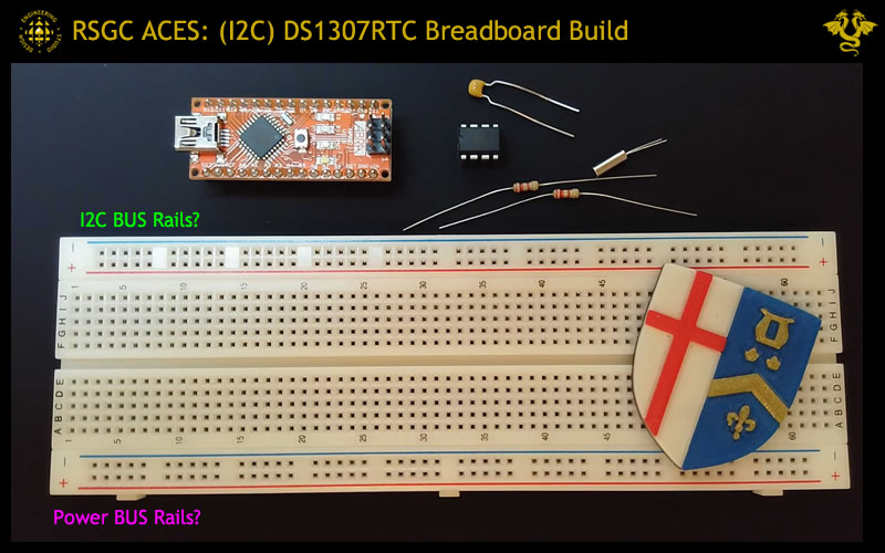
- Allocate some free breadboard space and wire up a simple I2C architecture using your Nano and DS1307 RTC as suggested below.
- Launch your Arduino IDE and open the Wire > i2c_scanner example sketch. Upload it to your breadboard Nano and open the Serial Monitor. If the IC is wired correctly the code will confirm the existence of ONE device.
- What appears to be the I2C bus address of your DS1307 RTC, in hex?
- Scavenger Hunt: Follow the link on our course page to the DS1307RTC datasheet to locate and confirm your RTC Address on the I2C Bus as reported by the I2CScanner sketch.
- Add the TC74 Temperature Sensor to your I2C bus and rerun your I2CScanner sketch. Confirm from page 9 of the TC74 datasheet that the I2C address is correct.
- Check out Digikey's Ordering options for the TC74 alone!
- Review the code and square up the statements in this sketch with the knowledge you have already gained from these few steps.
- If you're confident you understand how this scanner works, turn on your mic and be ready to explain it to your peers.