 Microchip's MCP4231 Digital Potentiometer.
Part A. Hardware I.
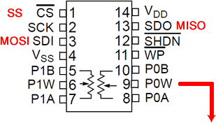
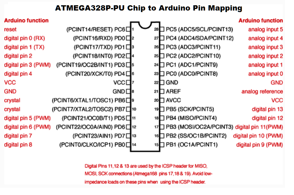
- Click on the pin diagram to the right (to enlarge) and confirm a mapping between the Arduino pin numbers and the MCP4231 pin numbers.
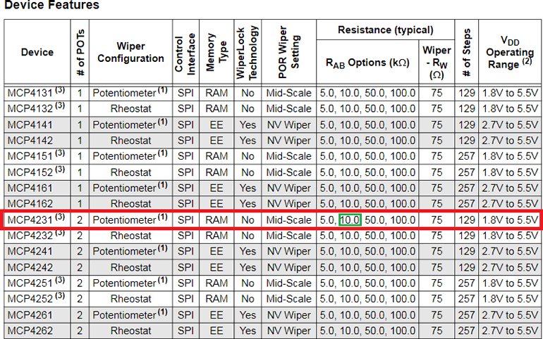
- Checking the features of this digital device (highlighted, below) reveals that you have control over 129 steps of resistance between 0 and 10 kΩ over a maximum operating range of 2.7 to 5.5 V.
- If the chip has a supply of precisely 5 V, determine the ΔV for each step.
- What conversion process is being undertaken within this device: ADC or DAC?
- Wire the Arduino and MCP4231 Potentiometer 0 together.
- Place an LED on Potentiometer 0's Wiper pin.

Part B. Software 1.
- Load the SPI Example sketch, DigitalPotControl. Save the sketch as SPIDigitalPotMCP4231 to your Arduino folder.
- This sketch is designed to control the 6-channel AD5206 digital potentiometer. Modify the code as necessary to control the MCP4231 to create a contiunous breathing LED effect on P0W, changing steps only every 100 ms. Modify the comments to fit the new IC and make any code efficiciency improvements (there are a number).
- Have your code write each value of the byte-size step data [0,128] to the Serial Monitor with every loop iteration and compare the value to the relative brightness of the LED.
- Upload and debug your code as necessary.
Part C. Hardware II and Software II
- Since the turn-on voltage of an LED is above 0 V, perhaps we should not waste power at these levels. Run your sketch a few more times, noting the approximate upward and downward threshold (step value) at which the LED transistions to OFF. Let's call this transition step.
- Assuming we are running our system at exactlly 5 V, what voltage level does the transition step correspond to?
- How could we modify our hardware and software efforts to address the transition so we ensure EVERY step of our digital pot influences a visible change in brightness?
- Perform these enhancements and note any performance improvements.

SPI Reference Material
Blum Chapter 9: The SPI Bus
 SPI, SPISettings
 The SPI Bus
 SPI Bus
 Microchip's MCP4231 Digital Potentiometer.
 Microchip's MCP4231 Digital Potentiometer.

![]() SPI, SPISettings
SPI, SPISettings