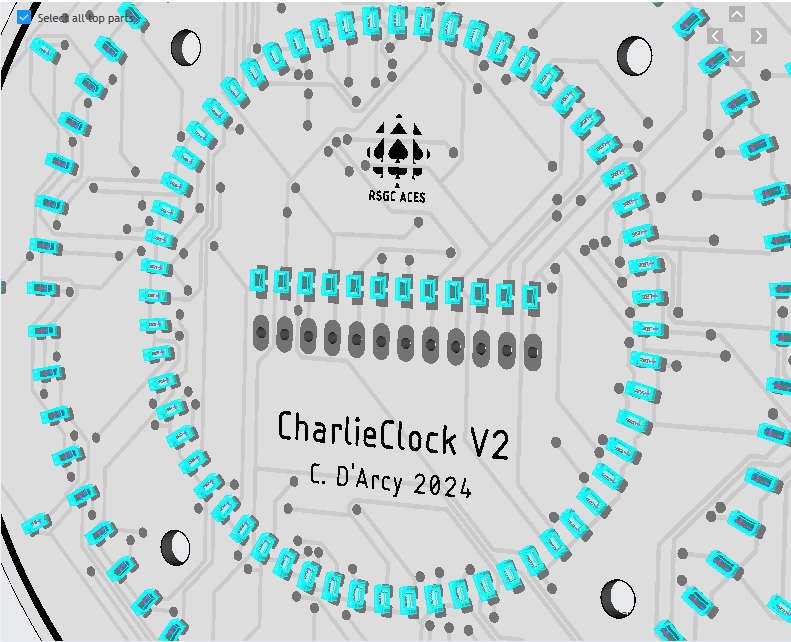
 ACES enjoy a rich history with Charlie Allen's discovery back in 2001. Charlieplexing offers both a practical and creative use of your MCU's tri-state digital pins and ACES have developed a number of devices that exploit its features (ie. CharlieStick, CharlieplexEqualizer). The 2022/2023 ICS4U-E ACES had the notion late in their year to develop a clock based on the principle and, although they scrambled at the end of the year to realize it, the course ended and it was off to summer and university without crossing the finish line.
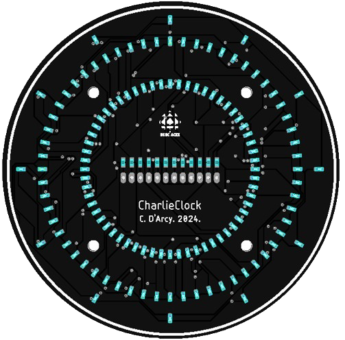
With a final three-hour class imposed upon the 2023/2024 ICS3U-E class, it was decided that an LED Charlieplex Clock was too irresistable to let sit on the drawing board for much longer. Mr. D. developed the PCB in late April and had JLC manufacture and populate 20 PCBs with 132 0603 LEDs (60 Red/Seconds, 60 Green/Minutes) and 12 Blue/Hours) in time for the final class of the year. Imagine, 132 LEDs driven by 12 tri-state digital pins. So good! Four mounting holes offers the motivated ACE the chance to develop and mount a driver circuit on the back or the front, over the summer. Hmmm.... come to think of it, digital date information would be a terrific complement to the analog time display. Furthermore, a stepper motor could rotate the day of the week into view, as do the Rolex; we'll call it the ACEX! Finally, a Fusion360 designed case would be a natural design enhancement. We'll see what my 2024/2025 ICS4U-E ACES show up with in September. They seldom disappoint :)
The Key to Charlieplexing: Tri-State Digital IO Pins
ATmega328P Datasheet: Chapter 14. I/O Ports

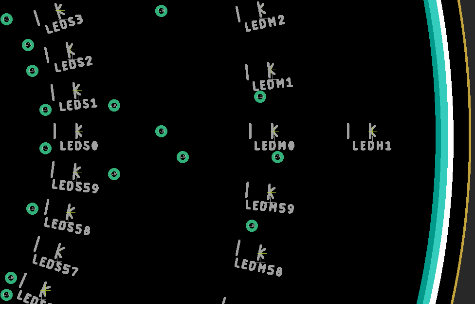
PCB Board View Clip
The greatest gift/benefit I can offer to those engineering-bound ACES with the courage, commitment and conviction to take this project on is to give you 'just enough' information to ensure that, when you eventually cross the finish line, you can, justifiably, call the achievement completely YOUR doing. To this end, here is a clip of the board view revealing the sequence of LED names that you can map/link/associate to the schematic above.
 Workshop Sequence
- (12:30) Review of the MCU's Tri-State Digital IO pins
- Math Concepts: Factorial, Permutations and Combinations
- Distribution and code development of the ACES 12-LED CharlieStick
- Demonstration of the 20-LED Charlieplexed Prototype
- Alternative #1. KIS. No RTC; simply 1s Timer1 Interrupts (pins 9&10) with H&M buttons (Ext Int. pins 2&3) for user adjustment)
Alternative #2. Date Feature? RTC. Adapt I2C RTC code from Term 2.
- --------------------- (1:50-2:05) BREAK --------------------------
- Pair up (Those going on matched with those 'retiring')
- Distribution and review of the ACES CharlieClock PCB
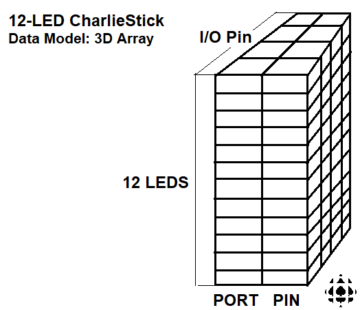
- Data modeling of the 132-LED clock
- Design inspiration: G. Davidge's 8-Channel Graphic Equalizer
- Hardware Option: Arduino Pro Mini for compact form factor
- (3:30) September Project Description and Farewells
Hardware Considerations
 Use this opportunity to push yourself into the use of SMT components for your PCB pursuits.
- Remember the DS1307 RTC from Grade 11? Well, here's how you can turn your ATmega328p into a similar RTC. If we instruct the ATmega328p to use its internal RC Oscillator instead of clocking it from the traditional 16 MHz crystal attached to PB6 (XTAL1) and PB7 (XTAL2), we're free to replace it with the 32.768 kHz, together with 12.5pF load capacitors. The oscillations can be tied to Timer2 asynchronously and trigger a TIMER2_COMPA_vect interrupt on each overflow. Read this application note for further details: AVR 130: Setup and Use of AVR Timers.
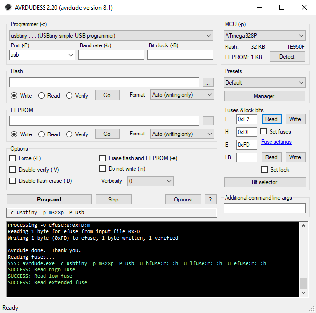
- To change the ATmega328p's clock source, one needs to modifiy the fuse bits. This can be tricky but I found a free useful application to achieve this. See AVRDUDESS.
Code Considerations
- Please use the corrected Data Model for V2.
Design Considerations
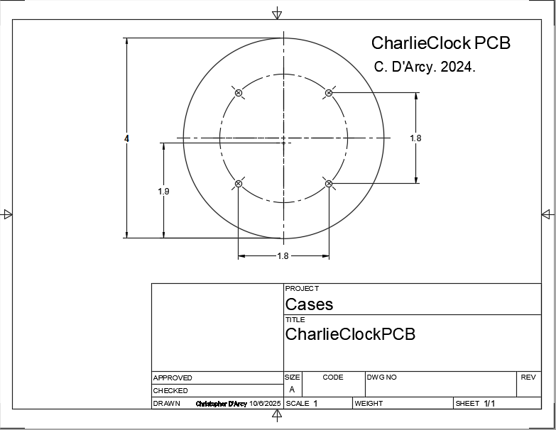
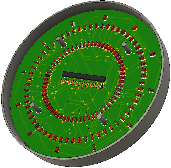
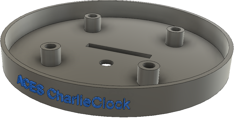
Designing an encasement to secure and display your CharlieClock offers the creative ACE a rich set of alternatives. Since additional circuitry can be mounted on the front or back using the PCB's four mounting holes offset 0.9 in from the center, you may wish to incorporate additional design allowances to contain the second populated PCB.
Finally, be sure to check out the straightforward Emboss feature of Fusion 360 to apply text to a curved surface, as shown below.
 ACES enjoy a rich history with Charlie Allen's discovery back in 2001. Charlieplexing offers both a practical and creative use of your MCU's tri-state digital pins and ACES have developed a number of devices that exploit its features (ie. CharlieStick, CharlieplexEqualizer). The 2022/2023 ICS4U-E ACES had the notion late in their year to develop a clock based on the principle and, although they scrambled at the end of the year to realize it, the course ended and it was off to summer and university without crossing the finish line.