2019/2020 ICS3U Challenge Exercise #2. Pierce Oscillator with LCD Display (inspired by J. Goodwin, ACES '22)
 A great many embedded systems projects (including the one we investigate on Friday of this week) depend on the measure of TIME. To ensure the most accurate monitoring of time, or timebase, electronics typically exploits the piezoelectric effect exhibited in quartz crystals in which a tiny amount of voltage is produced when the crystal is deformed. Conversely, when voltage is applied to the crystal, it deforms.
The circuit symbol for a crystal appears to the right.
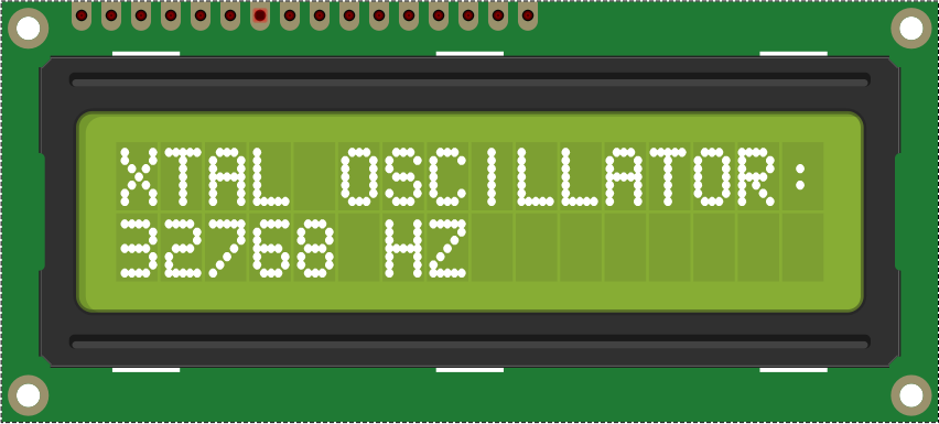 In this Challenge you will use your UNO (running to the beat of a 16 MHz Crystal) to monitor and confirm the accuracy of the 32.768 kHz crystal (and load caps) you have in your kit. Your goal is to capture the number of oscillations per second of the tuning fork crystal and update it every second on your LCD screen as shown EXACTLY to the right. The closer the count is to 32768, the higher the precision. Note that 32768 is 215, making it ideally suited for your MCU's binary manipulation abilities.
Your code design will also further reinforce your command of both External and TimerOne Interrupts.
Task.
 The Pierce Oscillator is a convenient subcircuit to convert the oscillations of your 32.768 kHz crystal into a digital square wave that can be fed into one (of your two) UNO External Interrupt pins, and monitored. Click on the schematic image to the right to enlarge.
- Your toolkit should provide you with the crystal, 12 ρF load capacitors, and 330 kΩ fixed resistor. Since I prefer absolute silence and can't always count on your kit being full and organized I'll loan you the parts. These are to be returned to me on Friday, in the foam, after a Show & Tell session at the start of class.
- Construct the Pierce Oscillator on your breadboard and feed its output to the UNO's External Interrupt 0 (digital pin 2). Wire in your LCD from the breadboard. Note. The appliance conflicts with the use of Digital pin 2 so you'll have to mount the LCD appliance on your breadboard.
- On the software side, your code will,
- Implement an external Interrupt Service Routine (ISR) to trigger on every FALLING edge of the incoming square wave from your Pierce Oscillator to enable you to count the edges.
- Implement a TimerOne library ISR to trigger an interrupt every 1s enabling you to report the count to the LCD screen (EXACTLY as shown above, right) and reset the count to 0. (Note. To present the most accurate count possible you need to consider the sequence in which your code's statements execute as this activity is highly time-sensitive)
- Finally, counts that deviate from EXACTLY 32768 will mean the clock you're basing it off of will be inaccurate. Now, there may be other local environmental factors influencing your count but you can, at least, ensure your code is counting EVERY POSSIBLE tick. Think.
- Once it's working, pinch either of the two fixed resistors to add your body's resistance to the oscillators. You should detect some slight deviations of the count.
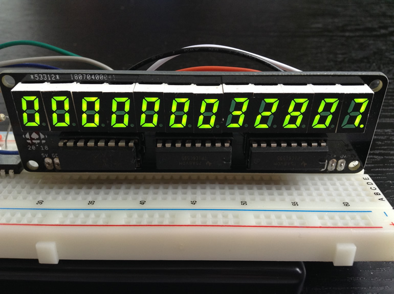
- Here's the count being displayed on the RSGC ACES' Beast...
 Finally, remember the DES is a drama-free zone.
Future Video:  How a quartz watch works - its heart beats at 32.768 kHz
Additional Reading: Quartz Clocks and Watches