(2024-25) Challenge 1. Driving a Passive PS1240 Piezo Buzzer Externally with a 555 Timer IC
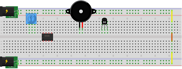
The datasheet for the passive PS1240 Piezo Buzzer recommends a voltage range of 3-30 V for the device and a driving frequency of between 2 kHz and 10 kHz. At 4kHz it yields the highest sound pressure of 70 dB.
The datasheet for the NE555 Timer IC recommends a maximum voltage of 18 V. Audio performance from the PS1240 varies directly with voltage. For this reason you are asked to configure an 18 V (±9 V) supply range on your breadboard as shown below.
Task.
- TBD...
(2023-24) Challenge 5. The IIlusion of Counting
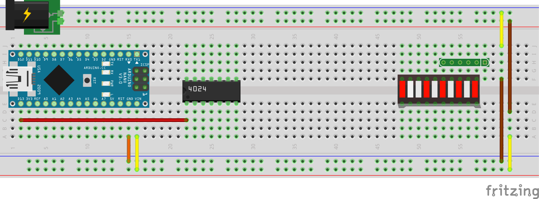
The Arduino's factory-flashed default Blink sketch provides a 0.5 Hz square wave on Digital Pin 13. This can be used as a clock signal source for the 4024 7-bit ripple counter IC. Exploiting the IC's frequency division capability, present an 8-bit counting simulation (0-255) on your single bargraph (or 8 LEDs).
As an added challenge, integrate the Nano's onboard Reset (Active LOW) button into the 4024's reset feature (Active HIGH) to clear the counting (0) at any time.
What if you sent the low nibble of the count through your 4511 to a 7-segment display? Be creative.
Send ONE Hi-Res photo of your circuit to ACESHandin by tomorrow (Tuesday October 31) by midinght. Here's a thought: Pimp your pumpkin: Finish it early enough and you could drop it in your pumpkin for the enjoyment of the little ghouls that drop by.... .
.
The best photo/circuit (creativity/build quality) will be posted on our course site on Thursday. Bring in your circuit on Wednesday both for confimation AND we'll be building off of it.
 Challenge 4. LCD CLock.
 Watch
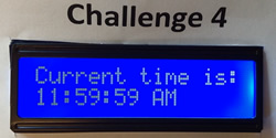
Watch  this video of a simple LCD Clock (with skill and a little luck you'll be able to watch your unit match the video sequence at the top of the hour). You are to duplicate it's presentation EXACTLY using your LCD module, 10k pot and other components in your toolkit. This is to include the EXACT text you see in the video. No latitude here.
- As you can see, the display updates every second. It will do so with the help of the timer interrupt ability provided through the use of the TimerOne library.
- As you can also see, the time is presented in the form HH:MM:SS followed by AM or PM. HH ranges from 1 to 12, inclusive (allow 2 places; no leading zero), MM and SS ranges from 00 to 59 inclusive (allow 2 places; leading zero if necessary).
- An additional requirement for your sketch is that the body of your loop() function is to remain ABSOLUTELY EMPTY as the entire functionality of your code is distributed amongst a set of single-purpose, methods.
- Remember to incorporate quality build practices and the elements of great coding style we've been highlighting this past week or so.
- There is only one evaluation of this challenge, in the final five minutes of the period. Restart your clock when I arrive at your station and have your Clock count from 11:59:45 AM.
Challenge 3. Reaction Timer with LCD Display.
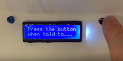 Watch this video of a simple reaction timer. You are to duplicate it's execution EXACTLY using the LCD module, 10k pot and other components in your toolkit. This is to include the EXACT text you see in the video. No latitude here.
- Using the data on the label of the bubble wrap packaging, you'll track down a straightforward tutorial on its wiring and access to sample driver code.
- Your evaluation is less about whether you can duplicate the result of the video (that's expected), but the strength of the techniques you employ. Hasty wiring and brute force code will earn an inferior result. Clean assembly and tight, efficient code that exploits as many of the concepts we have discussed will earn the higher credit.
- In the event your toolkit is 'component-deficient', you are NOT to raise your hand or leave your seat to go looking for a replacement. Simply place a substitute component in its place so that when I come around to your area on my video tour, the placeholder will inform me of your intent.
- Whatever you fail to complete during this period, you are to complete PRIOR to the START of Friday's class for another round of evaluation.
Challenge 2. Persistence of Vision, Part 2
- PoV is a technique many of you will likely incorporate into the display of your Musical/Audio project due later in the term (currently scheduled for March 7).
- You will be given a number of additional parts in class on Friday January 29 and the details of a task, not dissimilar to your previous PoV Challenge. You will undertake the challenge is the same manner as Monday, seated at your station until the exercise is completed or the end of the period, whichever comes first.
- Wise ACES always read the datasheet(s) thoroughly! Ask yourself how many hours you lost on the previous Challenge because of faulty assumptions.
- Another time killer: hasty, low-quality builds. Again, how much time was wasted ripping out sloppy wiring? Do it right > do it once.
- Everyone will leave their Arduino circuit power-ready for me as they leave the DES promptly at 12:30. I will evaluate what you were able to accomplish on your own. Return to the DES no sooner than 1:15 to collect your gear and be ready for a second evaluation at the start Tuesday's class.
- Your challenge is to present a stable duplication of the image (below, right) on your LED Matrix.
- Your supplemental Parts List includes the following,
1 |
Large Breadboard |
1 |
|
1 |
(additional) 74HC595 Shift Register
(you'll need two) |
20 |
3" (M/M) Jumper Wires |
|
 |
 Challenge 1. Persistence of Vision. This exercise will give you an indication of your level of competency with the concepts to date and in relation to your peers. You may wish to use the outcomes of this activity to gauge whether you're investing enough time and effort, both in class and after school, at staying on top of the concepts and hence the wisdom of electing to continue in the final year of our program. If at the end of this exercise you feel yourself lacking, there's time to do something about it as half the year is still ahead of us.
Some of the outcomes you should reflect on at the end of this exercise include,
- The responsibility of completing tasks that you were previously assigned for no other reason that you were asked to do so.
- The ability to maintain an active and independent competency with the concepts at all times.
- Your degree of connectedness and engagement in our program by how often you are reviewing our course page and email conferences. For example, I am posting this page on Saturday January 23 at 6 pm. If you are reading this for the first time after having just sat down for Period 3 on Monday January 25, well ...
- The ability to read and comprehend the description of a technical task and to understand its expectations without the need for additional clarification or interpretation.
- The organization of your toolkit and other resources.
- The ease and efficiency with which you can complete the task.
The Challenge.
- You are to complete this task on your own. You are not to ask a friend for assistance, or me.
- Everything you need to complete this task, except one additional part that you will be provided with, is in your toolkit. If they are not, or your toolkit is in your locker, or worse, at home, you are not functioning to an acceptable level of expectation.
- You are expected to complete this task by the end of the period. If you finish before 12:30 raise your hand and I will come to your desk for your demonstration. If it is successful, you may leave for an early lunch. You get one chance for a demonstration; if it was unsuccessful you are to remain for the balance of the period.
 All ACES are expected to have completed this challenge, on their own, for the START of Wednesday's class, at which point I will you and record the extent of your success.
- You are to remain in your seat for the duration of this task. If your kit is missing a component, simply wire everything else and complete the task after class, before Wednesday.
- Your current circuit is driven by a sketch that defines a bit→segment map for the 10 decimal digits and employs a SINGLE 74HC595 Shift Register to cycle continuously through the SINGLE digits from 0 to 9 on a SINGLE common cathode 7-segment display. Let's define this task by the ordered triple,
(MAP, SHIFT, DISPLAY) = (SINGLE, SINGLE, SINGLE).
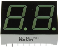
- You have been provided with the DUAL seven-segment display device pictured to the right. Source its datasheet on the internet and familiarize yourself with the pin mapping.
 Your task is to implement the sketch Dual7Segment.ino that will use the same SINGLE bit→segment map and the same SINGLE 74HC595 Shift Register to cycle continuously through the numbers from 00 to 99 on this DUAL device. Let's define this task by the ordered triple,
(MAP, SHIFT, DISPLAY) = (SINGLE, SINGLE, DUAL)
Your task is to implement the sketch Dual7Segment.ino that will use the same SINGLE bit→segment map and the same SINGLE 74HC595 Shift Register to cycle continuously through the numbers from 00 to 99 on this DUAL device. Let's define this task by the ordered triple,
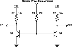
(MAP, SHIFT, DISPLAY) = (SINGLE, SINGLE, DUAL)- To do so will require a persistence of vision strategy that will employ one additional Arduino data pin that will supply a square wave (HIGH,LOW,HIGH,...) to the base pins of an NPN and PNP transistor (3904 and 3906), effectively alternating between displays.
- The counting should be undertaken a 1Hz (one second interval per number). Adjust the frequency of the square wave so the eye does not detect any flicker (>>24 Hz).
- A video of the display counting from 00-99 is scheduled for viewing at 12:30 PM today: PoV: Dual 7-Segment Display.