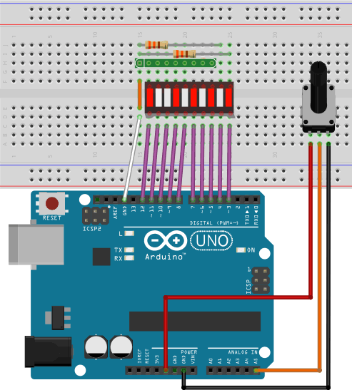
 Grab your bargraph, 330 Ω 9-pin (8 bussed) resistor network, two other 330 Ω fixed resistors in order to assemble the prototype to the right EXACTLY as shown (this will help you get more out of what follows).
 - The bargraph is an example of a 1-dimensional array. Are there other examples of arrays in the image?
- Open the Arduino IDE and load the sketch: File > Examples > Display > barGraph
- Save the sketch as MyBarGraph and make all necessary edits (and improvements) to have it comply with YOUR prototype.
- Execute the sketch and manipulate the potentiometer to confirm the LED behaviour.
- Move your power source to 3.3 V. Run the sketch again. Edit your code to realize the full range of LED under 3.3V.
- See Section A.8.1.1 Mathematics: Binary Display on p. 19 of our workbook. Create a new sketch entitled BinaryDisplay and fulfil the requirements of the task.
- Save your sketch as BargraphAnimations and try your hand at duplicating as many of the animations depicted in thie video
 Bargraph
Animation Exercises as you can.
Bargraph
Animation Exercises as you can.
Using Arduino's Arrays Reference and Tutorial, implement code for each of the following tasks.
- Create a new sketch under the name BargraphExercises.
- Define and declare an integer array consisting of the 7 active pin numbers.
- In setup(), declare the pin mode for each the active pins as OUTPUT.
- In loop(), add two statements (only) that will result in all seven pins being lit.
- Reorganize your code so that the two statements added in the previous step are repackaged within the no arguments function, allOn(). Call the function from the loop() function to confirm. Since the function has no arguments, the array data it needs are accessed as a global resource. This is not the preferred design decision the long run, but we'll overlook it for the time being.
- Develop and debug a no-argument function, allOff().
A bargraph can be used in either Dot or Bar Mode. In Dot mode, only a single LED is lit. In Bar mode, all LEDs are lit from the first to the n'th. Note: The natural numbering of the LEDs in a bargraph would be 1 through 10. Array indices are 0-based. Your code will need to account for this discrepancy.
 Develop and debug the one-argument dotOn(int n) function that turns on the n'th LED only. Develop and debug the complementary function, dotOff(int n).
- Develop and debug the function, dotTest(int n), that exercises the bargraph in Dot mode from LEDs 1 through n and back again, as depicted in the first of the two adjacent animations.
 Develop and debug the function, barOn(int n) that lights the LEDs from the first to the n'th. Develop and debug the complementary function, barOff(int n).
- Develop and test the no-args function, barTest(), which exercises the bargraph in Bar mode from 1 through 7 and back again, as depicted in the second of the two adjacent animations.
A byte is an 8-celled array of bits and used as a compact model of the state of 8 I/O pins, or more. The two possible values of an individual bit can be interpreted as HIGH or LOW. To exploit this data efficiency, access the individual bits in a byte is required. Start with a review of the Arduino Language's Bit and Byte Manipulation resources (halfway down on the right).
 Declare and define a byte-sized variable, value, using Arduino's Integer Constants syntax.
- Familiarize yourself with the concept of Bit Masks.
- Develop and define the one-argument function, display(byte value), that lights the dots on the bargraph that correspond to the set (1) bits in the value parameter. Be sure to use previously developed functions to assist in the task.
Serial Communication with the Arduino.
Data can be transmitted to and from the Arduino to the IDE's Serial Monitor. Familiarize yourself with the Serial Library. In particular, look deeply into the explanation and examples provided for the begin(), available(), read(), print() and write() functions.
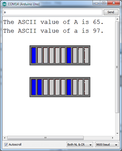
- Exploit the ability of the Arduino to read from and write to the Serial Monitor that results in the ASCII value of character entered to be echoed on the Serial Window. Also display the ASCII value on the bargraph as depicted. Be sure to exploit as many of the functions you have previously developed.
Compared to a laptop, the limited resources of a microcontroller require the competent developer to have a sound knowledge of low-level bit manipulation techniques in order squeeze the most performance from the device.
- Familiarize yourself with the Arduino languages overloaded Random() functions. Create a sketch entitled BitBanging and develop high quality code that will display a random byte in the closed interval, [32,127], in both decimal and its binary equivalent, one per line, every 2s. Take steps to ensure that the binary equivalent shows ALL 8 bits.
- Add code to your BitBanging sketch that counts and display the number of set bits (1s) in each of the random number and provides a well-formed sentence indicating the number and the count.
- Read this page on the concept of a parity bit. Add code to your BitBanging sketch that modifies the binary equivalent of the random byte for potential transmission under an even parity scheme.