 Arrays and Structs fall into the category of Data Modeling.
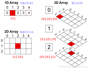
Single (1D) Arrays (aka Vectors)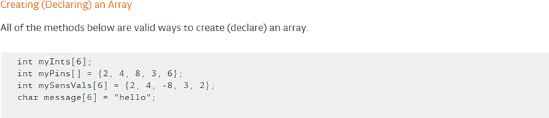
 Create a sketch entitled Arrays.ino.
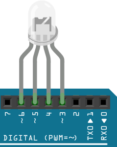
- Insert your RGBLED into your Arduino as shown, with the CC lead (longest) in pin 4.
Parallel Arrays (not ideal)
- Define an array of type uint8_t, with the variable name pins, and populate the array with the values 3, 5, and 6.
- Define an array of type uint8_t, with the variable name state, of length 3, but do not populate the array.
- Define the uint8_t variable, len, and initialize it to the length of the state array, the best way possible.
- Define pin 4 as the ground pin.
- In the setup() function assign random HIGH or LOW values to each of the cells in the state array. Display the values to the Serial Monitor and write the corresponding state to each of the pins for confirmation.
- Are the values random? Modify your code so that it is.
Structs: Tighter Binding (better)
Let's explore a better technique for binding the pin number with it's initial state more tightly using the struct data structure.
- Comment out the array data model definitions in the previous code.
- Define the struct pin that encapsulates the pin number with its state (as in an ordered pair).
- Define the array pins of base type pin and hard code the contents as ordered pairs, randomly assigning a 0 or 1 to the state field.
- Modify the code in your setup() function to adapt the new syntax and execute your sektch.
- Finally, since the anode pins in use are all PWM pins, we can randomly assign the state field a value on te closed interval [0,255] and switch to analogWrite() as our output method. Do this and confirm the results.
Let's move on to 2D arrays (matrices)....
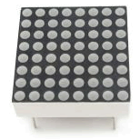 Look at the image of the 8x8 LED Matrix to the right. You have one of these in your kit. This device can be thought of as a 2D arrray with 8 vertical columns and 8 horizontal rows. We could model this in software as,
uint8_t matrix[8][8]; //one BYTE per LED
Alternatively, we could model this LED display as a 1D uint8_t row array with each column in the display represented by a bit in each of the 8 bytes. This gives of 64 bits in total which exactly matches the number of LEDs in the device.
uint8_t matrix[8]; //loosely interpreted as a matrix but only requires one BIT per LED
This is closer to how we're going to code it because there is a significant savings in RAM requirements.