Concepts Grade 11 ACES Should Know
 Microchip's 8-bit AVR series of MCUs have THREE on-board, fixed-sized, memory areas. The sizes of these byte-addressable storage locations vary depending on the MCU (Tiny, Mega, XMega, etc.).
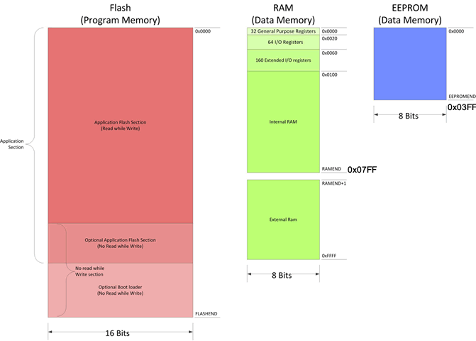
Basic details of the ATmega328P employed by the Arduino UNO and Nano are shown to the right (click to enlarge). Here are a few more insights into the primary uses of these three memories.
- Program Memory (FLASH). By far the largest of of three, the RED area is where your executable code is uploaded to and executes from. Bytes are paired to create Word-size (2 Byte) addresses to accommodate 16-bit instruction codes.
- Static Random Access Memory (SRAM). When your program executes, any requested storage for global and/or local variables is located within the GREEN area, referred to simply as RAM. When power is removed from the Arduino, data values of these variables is lost, hence the term, volatile is applied to RAM.
- Electronically Erasable Programmable Read Only Memory (EEPROM). By far the smallest byte-sized storage area, the BLUE area, EEPROM, can be used to store data that needs to be retained (persistent) during program execution and after power is removed from your device. The term non-volatile is applied to EEPROM.
The simplest techniques for modeling data involves setting aside RAM by declaring variables to be a type chosen from one of the languages simple data types. Here's one of many references. For the discussion that follows, we'll consider the specific size of SRAM in your ATmega328P.
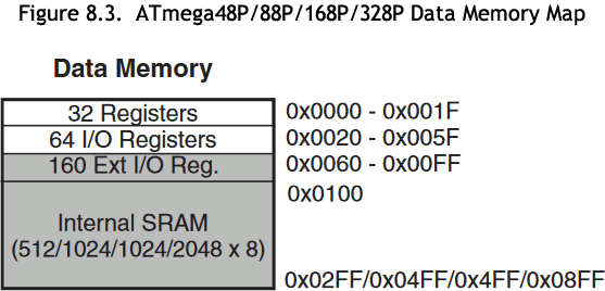 First off, the ATmega328 datasheet indicates that the complete storage capacity of SRAM is 2 KB (2048). Byte values are accessed by address, just like mailboxes at the post office. Since the entire address space is 211 bytes in length, the first address is 0x0000 and the last is 0x08FF.
As it turns out, the MCU hardware requires 256 Bytes of storage space for its own purposes and takes it off the top, from addresses 0x0000 to 0x00FF. This is not too much of a penalty as it leaves addresses 0x0100-0x08FF for your code's variables.
Data Modeling 1.
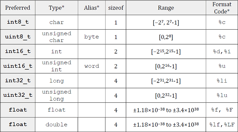
The important table below can be found on page 7 of your AVR Foundations Workbook. It provides a brief summary of the more common simple data types, their SRAM memory requirements (in bytes) and the range of values that can be represented in variables of the respective types.
In most cases the amount of available SRAM far exceeds the demands of your code's variables. It's interesting to examine the toolchain dialog at the bottom on your IDE that appears as your program goes through the execution cycle. You'll gain an appreciation of the percentage of RAM your code is using.
Data Modeling 2. Collections: ARRAYS
 Programming contexts that would benefit from multiple data of the SAME TYPE being bound together as a single collection, suggest a structure known as an array.
- Syntactically, an array of elements can be defined by a sequence of comma-separated data values, enclosed in brace brackets, { }
- Arrays require the use of the (suffix) [ ] subscript operator to identify which member (element) of the collection is being referenced.
- As a unary operator, you'll see from the Table of Operator Precedence, the subscript opertor [ ], is in the group of the 2nd highest priority!
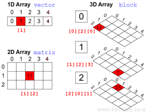
- Arrays can be multidimensional. For example,
- Your bargraph is a one-dimensional array of LEDs. A one-dimensional array can be referred to as a vector.
- Your small LED matrix is a two-dimensional arrays of LEDs, consisting of 8 horizontal rows and 8 vertical columns. Here's a very useful thought: a matrix is a vector of vectors.
- The calendar that hangs in your kitchen can be thought of as a three-dimensional array in each of the 12 months consists of a two-dimensional array with 5 weeks (rows) and 7 days (columns). Again, a three diemnsional array is but a vector of matrices (plural of matrix).
- Look around you (the DES, your home, the post office, the lobby of an apartment building, etc). There are many examples of multidimensional collections of homogeneous (same type) data all around us.
- Each array dimension requires a separate (suffix) [ ] operator.
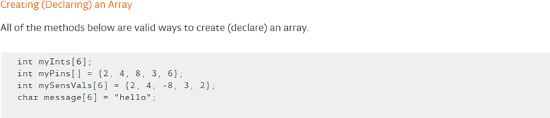
- Here are some examples of one-dimensional array declarations taken from the Arduino tutorial,
2022/2023 ICS3U 1D ARRAY Examples and Exercise
First Off: Inspirational Array Applications (LED Displays (Segment Maps, LookUp Tables (LUTs)))
 74HC595 Shift Register Bargraph (74HC595ShiftRegisterArrays.ino)
- CMOS 4511 Aternative: Segment Map (LUT) for Decimal Digits on a 7-Segment Display (7SegmentShiftOutSRAM.ino)
- Segment Map (LUT) for Hexademical Digits on a 7-Segment Display (7SegmentShiftOutSRAM.ino)
- Segment Map (LUT) for Uppercase Letters on a 7-Segment Display (7SegmentUpperCaseLetters.ino)
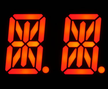
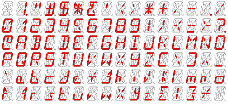
- Display from a uint16_t Segment Map (LUT) on your 14-Segment Display (15SegmentUppercaseLetters.ino)
(click image bottom left for the datasheet; click image to the bottom right for full ASCII Segment Map)
- Serial Input and display from a Segment Map (LUT) on a 7-Segment Display
- Serial Input and TBD...
Array Exercise: Sensor Monitor
For some of you, the code and in-class demonstrations presented above provide sufficient context from which to launch your own array investigations. For the rest of us, we benefit from the blank canvas, ground up approach to arrays. In addition, this exercise should provide every skill level with useful techniques and strategies.
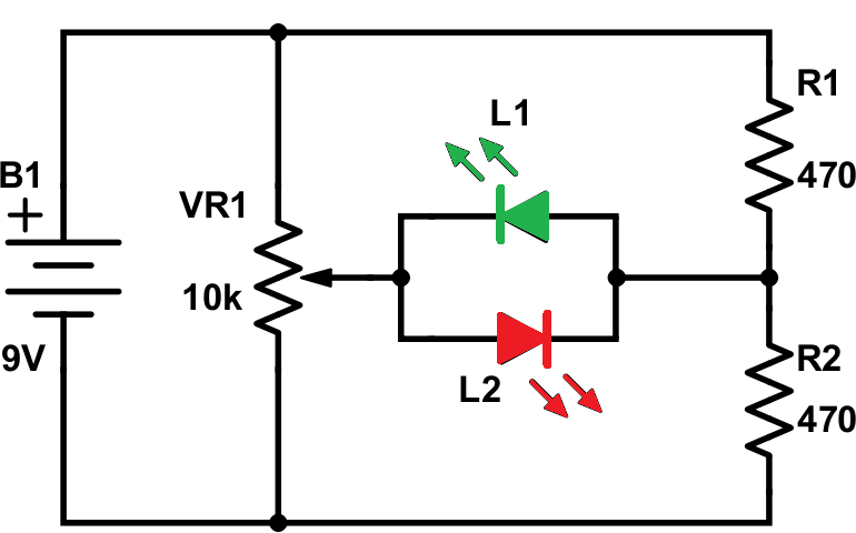
In Grade 10, one of the first concepts introduced was that of a Voltage Divider. In this exercise we use a simple voltage divider to gain facility with the coding of arrays.
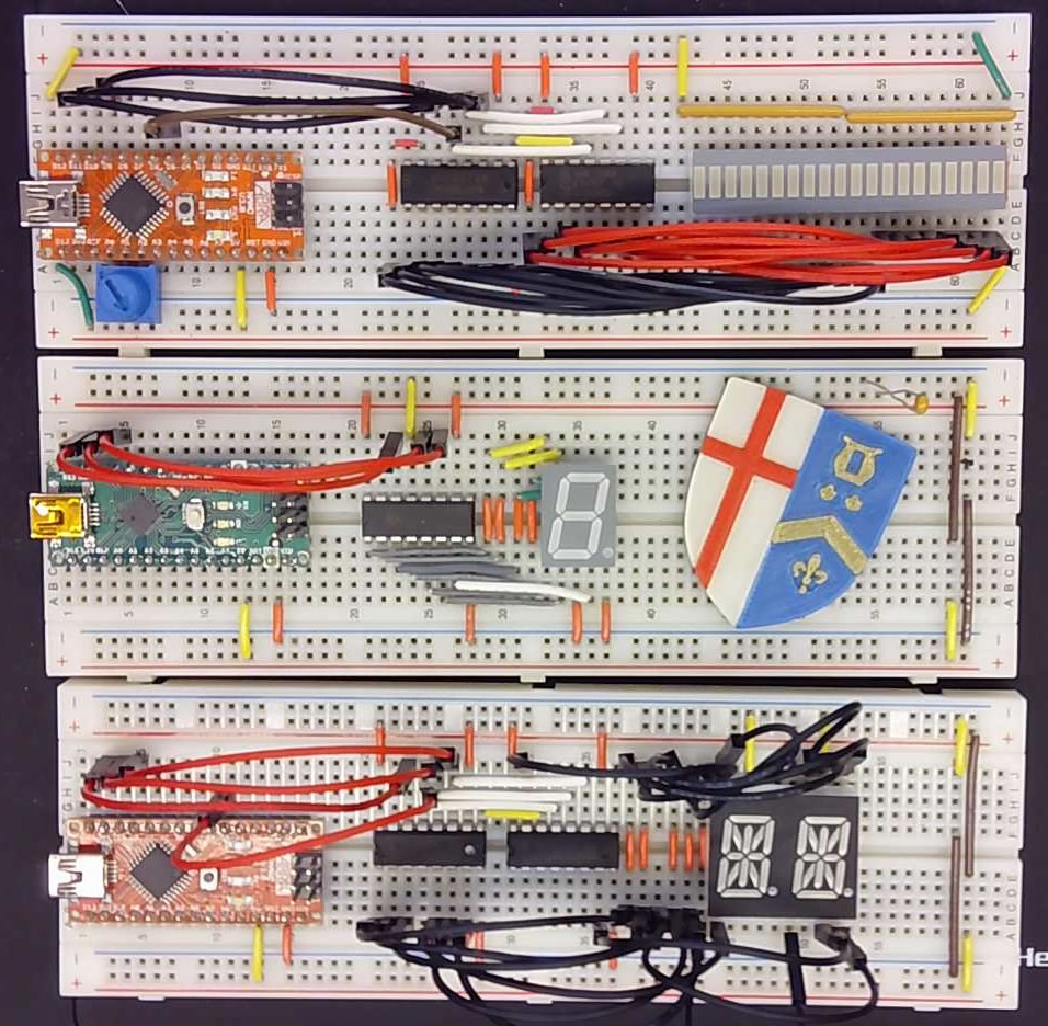
- Assemble the simple prototype shown below that presents a voltage divider using a 10 KΩ fixed resistor and your LDR on the A0 pin of your Nano (or UNO)
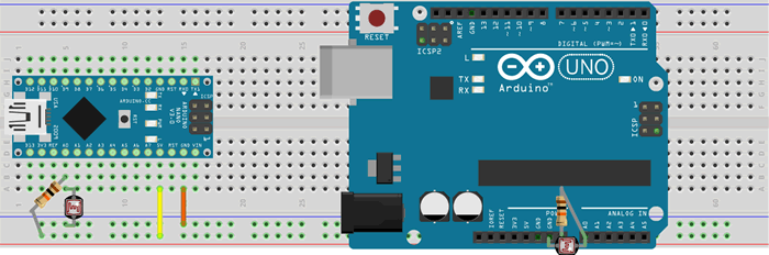
.
- We need the services of the Serial Monitor and Plotter for this task so be sure to have the bootloader installed on your Arduino (put it on with your Sparkfun AVR Pocket Programmer) before connecting your USB/Serial Cable to your device.
- Create an Arduino project called, SensorMonitor.
- To start with, employing your STRONGEST coding skills, lay in the software foundation to simply acquire and echo raw analog readings, continuously.
- Upload with Tools: Programmer: AVR ISP
- Launch the Serial Monitor. Wave your hand over the LDR and observe the range of readings.
- Launch the Serial Plotter. Wave your hand over the LDR and observe how the graph responds.
- Place a 100 ms delay between readings before relaunching the Serial Plotter. That's more like it...
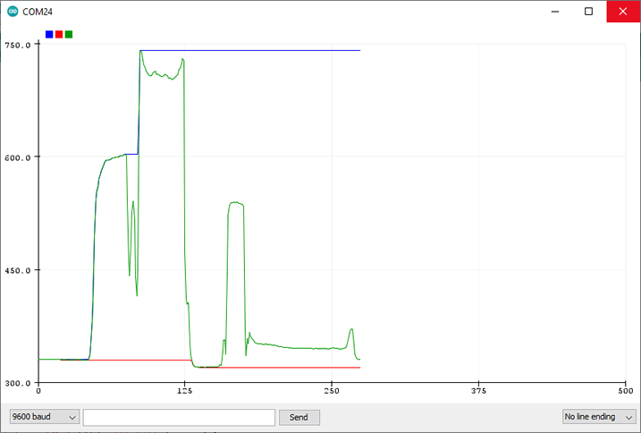 The Serial Plotter can plot multiple graphs. The plot to the right tracks and presents 3 graphs: The maximum reading (BLUE), the minimum reading (RED) and the current reading (GREEN). Let's recreate this plot.
- Add two new uint16_t variables called minimum and maximum, initializing them to 1023 and 0, respectively. Note. By starting each one off at its opposite extreme we guarantee our empirical readings will modify their initial values.
- Add statements to update and display each of the three data streams. We'll do this together. Launch the Serial Plotter to test. Screen captures of plots can support your future DER submissions in a very positive way.
History Lists (Moving Averages) and Plotting
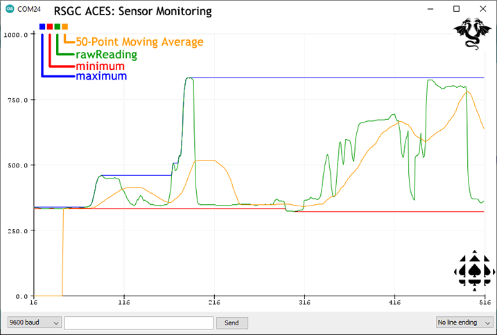
OK, now we're ready for the array enhancement to the project. The concept of a Moving Average (10-day, 20-day, 50-day, etc.) is used by investors to signal longer term price trends beyond just the previous day's Closing price. In this final segment of the exercise, we maintain a recent history of readings in an array to determine a multi-day average of the history. We also present this as a fourth graph (ORANGE). Here's our strategy/algorithm,
 Using a preprocessor directive, define DATASIZE for the size of the array. Let's start with 50.
- Declare the array, history, with a base type of uint16_t, of size, DATASIZE. We'll use this array (data structure) to store the most recent (DATASIZE) readings acquired from our (voltage divider) sensor.
- Within the setup() function, populate the history array with all 0s, though the use of a for loop.
- Within the loop() function, add code that will store each new reading in the next available cell of the history array. Use the modulo operator (%) to enable the index to wraparound to 0 when it reaches the last cell, thereby supporting the 'moving' average.
- Create a function with header, uint16_t getAverage() that computes and returns the average of all the elements in the history array. Call the function after each new reading.
- Add a fourth graph to your plot of the moving average. Click on the image to the right to get an idea of what we're aiming for.

Let's move on to 2D arrays (matrices)....
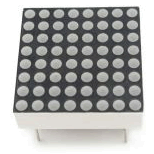 Look at the image of the 8x8 LED Matrix to the right. You have one of these in your kit. This device can be thought of as a 2D arrray with 8 vertical columns and 8 horizontal rows. We could model this in software as,
uint8_t matrix[8][8]; //one BYTE per LED
Alternatively, we could model this LED display as a 1D uint8_t row array with each column in the display represented by a bit in each of the 8 bytes. This gives of 64 bits in total which exactly matches the number of LEDs in the device.
uint8_t matrix[8]; //loosely interpreted as a matrix but only requires one BIT per LED
This is closer to how we're going to code it becuase there is a signifincant savings in RAM requirements.
 74HC595 Shift Register Bargraph (74HC595ShiftRegisterArrays.ino)