 As you are aware, the heart of the Arduino UNO is the ATmega328P. As you can see from its datasheet it offers a lot of features and, as such, is a reasonable choice for a multipurpose development board.
 | RSGC ACES: When an ATtiny may be the better option... |
As you are aware, the heart of the Arduino UNO is the ATmega328P. As you can see from its datasheet it offers a lot of features and, as such, is a reasonable choice for a multipurpose development board.
In situations where an embedded system has a limited task to perform you way wish to consider a different microcontroller from ATMEL's vast product portfolio. The tiny line of uCs have fewer resources but also a much smaller footprint and reduced power requirements, operating with as little as 1.8V.
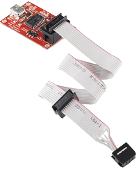
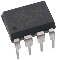
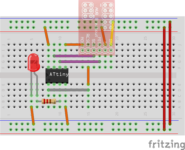
The ATtiny85 is one such device in this line. Here's a YouTube video that uses your Arduino as the programmer for the ATtiny85. In this introduction, we'll first demonstrate how to program the device using an AVR Pocket Programmer through the Arduino IDE and, later, from the Mac's command line Terminal utility using C. Here's the additional hardware that will simplify the task,
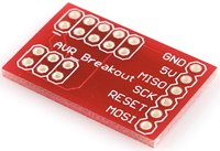
| AVR Pocket Programmer | AVR Breakout Board | ATTiny85 |
|---|---|---|
 |
 |
 |
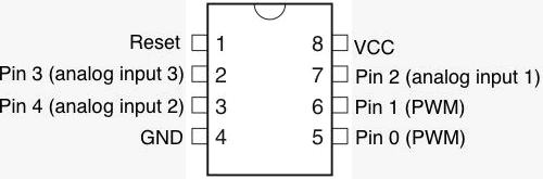
| ATtiny85 Pinout |
|---|
 |
Technique #1. Arduino IDE
Technique #2: Terminal and avr-gcc