

| RSGC ACES: 555 Monitoring, Analysis and Application (November 2025) |
The monitoring and analysis of both analog and digital signals is best achieved through the use of sophisticated devices like oscilloscopes and frequency generators. Given that it is not practical to equip each ACE with $1000s worth of these devices students must emulate these tools the best they can with the resources they have in their kits and can engineer. Through deep thinking and creativity the gaps can be narrowed. Let's exploit the 555 Timer IC's capabilities in support of an approach to monitoring and analyzing it's analog and digital behaviour.
Below left is a screen capture of Ben Eater's classic Youtube introduction to the Astable 555 Clock circuit. Below right is a typical schematic of the 555 in astable mode. Through the use of your Nano's analog and digital capabilities, together with the builtin Arduino software functions and Serial display utilities, the 555 can be modeled fairly accurately.
| B. Eater's Astable 555 Clock Circuit | 555 Schematic |
|---|---|
|
|
Investigations
1. Simple Monitoring and Plotting Using AnalogRead and DigitalRead Functions
555 Configuration: R1=1 kΩ, R2=100 kΩ and C1=1 μF.
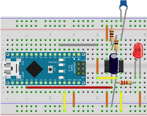
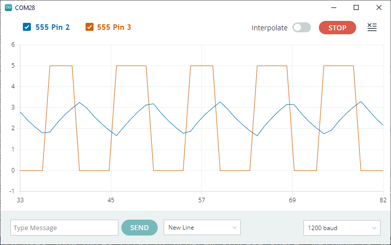
For our first investigation we'll simply wire a Nano's analog pin A0 to the 555's Pin 2 (analog monitoring of C1) and the Nano's digital pin 2 to the 555's pin 3 (digital monitoring of the output of the inverter). A breadboard layout could appear similar to the one shown below, left. Upload the code that appears below and launch the Serial Plotter. I've commented out the display of the legend as the time it takes to transmit reduces the quality of the analog and digital sampling. As could be expected, the voltage range of the capacitor is restricted to [Vcc/3,2Vcc/3] whereas the voltage range of the inverted spans the entire [0,Vcc].
| Nano Monitoring of the 555 | Arduino Plot |
|---|---|
 |
 |
// PROJECT  : 555Monitor
// PURPOSE  : Captures the oscillations from the 555 and converts them to a frequency
// COURSE   : TEJ3M
// AUTHOR   : C. D'Arcy
// DATE     : 2025 11 17
// MCU      : 328p (Nano)
// STATUS   : Working
// REFERENCE: https://www.allaboutcircuits.com/tools/555-timer-astable-circuit/

#define DIGITALCAP 2      //Monitor 555_3 on Nano_2
#define ANALOGCAP A0      //Monitor 555_2 on NAno_A0
#define VCC 5.0           //Voltage supply maximum

void setup() {
  Serial.begin(9600);
  while (!Serial) {}
}

void loop() {
  // Serial.print("555_Pin_2:");  //Printing the Legend slows down the display
  //Serial.print(analogRead(ANALOGCAP));
  Serial.print(VCC * analogRead(ANALOGCAP) / 1024);
  Serial.print(',');
 // Serial.print("555_Pin_3:");                   //Printing the Legend slows down the display
  Serial.print(VCC * digitalRead(DIGITALCAP));  //Scale it to stabilize the Serial plotting
  Serial.println();
}
2. Frequency Confirmation Using PulseIn
 Our second investigation attempts to confirm the expected frequency of oscillation on pin 3 of the 555 using the (unusual) pulseIn() function. This (blocking) function monitors the amount of time, in microseconds, it take to transition either from HIGH to LOW or LOW to HIGH, depending on what is sought. No change is required to your prototype.
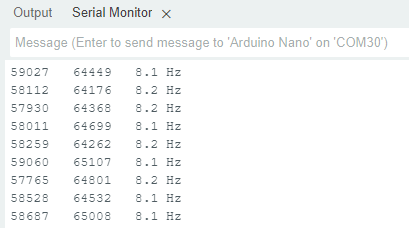
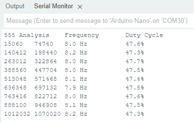
Using the code that appears below, together with the same program components as in the previous investigation (R1=1 kΩ, R2=100 kΩ and C1=1 μF), the results obtained are presented to the right. The data in the first two columns are the HIGH and LOW times in μs, respectively. The period can then be determined and the frequency evaluated for the third column.
Let's see how these results compare to expected results.
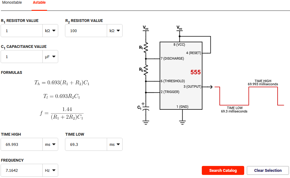
Using Digikey's 555 Timer Calculator in Astable mode suggests the expected frequency result shown below left and the time HIGH and LOW, below right. These outcomes suggest we're in the right ballpark.
// PROJECT  : 555MonitorPulseIn
// PURPOSE  : Monitoring the frequency of the 555
// COURSE   : TEJ3M
// AUTHOR   : C. D'Arcy
// DATE     : 2025 11 17
// MCU      : 328p (Nano)
// STATUS   : Working
// REFERENCE: https://forum.arduino.cc/t/measuring-frequency-of-sine-wave/298450/5
uint32_t input = 2;
uint32_t high_time;
uint32_t low_time;
float time_period;
float frequency;
#define INTERVAL  500

void setup() {
  Serial.begin(9600);
  while (!Serial) {}
}

void loop() {
  high_time = pulseIn(input, HIGH);
  low_time = pulseIn(input, LOW);
  Serial.print(high_time);
  Serial.print('\t');
  Serial.print(low_time);
  Serial.print('\t');

  time_period = (high_time + low_time); //
  time_period = time_period / 1000;     //
  frequency = 1000 / time_period;       //

  Serial.println(String(frequency, 1) + " Hz");
  delay(INTERVAL);
}
3. Frequency and Duty Cycle Confirmation Using Interrupts
 Since the pulseIn() function blocks your program from doing anything else it is not the most efficient. Enter: Interrupts.
Reference: attachInterrupt()
The Interrupt mode of programming MCUs allows your system to carry on with any or all active tasks within the need to check in periodically if the servicing of an action is required. When attention is needed to service a request for action, the current ongoing state of your system can be saved until the service request is satisfied, before returning to 'our normally scheduled program'. In this way it is somewhat like an alert on our phones just like a Weather Alert, Amber Alert or Hydro Alert. We never know precisely when it arrives but, when it does, it takes over our resources, prior to returning control to whatever we were doing. No modifications to your prototype from Step 2 are required.
The results obtained from the Interrupt code below appear to the right.
// PROJECT  : 555MonitorInterrupts
// PURPOSE  : Monitors a Square Wave Oscillation signal for Frequency and Duty Cycle
// COURSE   : TEJ3M
// AUTHOR   : C. D'Arcy
// DATE     : 2025 11 17
// MCU      : 328p (Nano)
// STATUS   : Working
// REFERENCE: https://docs.arduino.cc/language-reference/en/functions/external-interrupts/attachInterrupt/
// REFERENCE: https://www.digikey.ca/en/resources/conversion-calculators/conversion-calculator-555-timer
// NOTES    : Monitors 10 periods. Good application for External Interrupts
#define EXTINT0 2
#define BAUD 9600
volatile int16_t count = -1;
volatile uint32_t rising[10] = { 0, 0, 0, 0, 0, 0, 0, 0, 0, 0 };
volatile uint32_t falling[10] = { 0, 0, 0, 0, 0, 0, 0, 0, 0, 0 };
uint8_t periods = sizeof(rising)/sizeof(uint32_t);

void setup() {
  Serial.begin(BAUD);
  while (!Serial) {}
  attachInterrupt(digitalPinToInterrupt(EXTINT0), ISR_Rising, RISING);
}

void ISR_Rising() {
  count++;
  rising[count] = micros();
  attachInterrupt(digitalPinToInterrupt(EXTINT0), ISR_Falling, FALLING);
}

void ISR_Falling() {
  falling[count] = micros();
  attachInterrupt(digitalPinToInterrupt(EXTINT0), ISR_Rising, RISING);
}

void loop() {
  if (count == periods-1) {
    detachInterrupt(digitalPinToInterrupt(EXTINT0));
    Serial.println("555 Analysis\tFrequency\tDuty Cycle");
    for (uint8_t i = 0; i < periods-1; i++) {
      Serial.print(rising[i]);
      Serial.print('\t');
      Serial.print(falling[i]);
      Serial.print('\t');
      Serial.print(1E6/(rising[i+1]-rising[i]),1);
      Serial.print(" Hz\t\t");
      Serial.print(100.0 * (falling[i] - rising[i]) / (rising[i+1] - rising[i]),1);
      Serial.println('%');
    }
    while (1) {}
  }
}
4. 555 Application: Square Wave to Sine Wave
 It is hard to overstate the importance of sinusoidal waves in our modern world. Those ACES looking to electrical undergraduate engineering will be particularly interested in their generation and analysis. The 555 Timer IC can provide us with fundamental square wave that can be manipulated into sinusoidal behaviour in any number of ways. The strategy that is most accessible to us at our desks is through the use of simple passive components. We'll employ resistors and capacitors in our kits to form what is know as a passive low pass filter network.
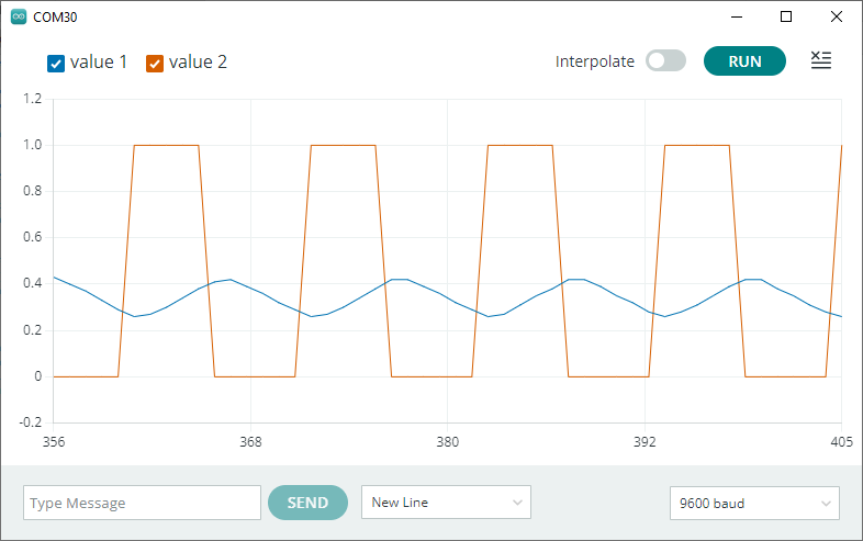
The initial goal of this task is to continue to have our Nano monitor and plot both the input 555 square wave and the output sinusoidal wave of our (3-pole) passive low pass filter network as shown in the graphic to the right. It is easily noted that there is significant attenuation (loss) of the signal's amplitude (strength) as a result of it passing through the network. Restoration is a topic for another day.
Reference 1: ACES FramePlayer: Square Wave to Sine Wave
Reference 2: (Must Watch)![]() How Low Pass Filters Work
How Low Pass Filters Work
Reference 3: How to Build a Square-to-Sine-Wave Converter Circuit
Reference 4: Digikey's Low Pass/High Pass Filter Calculator
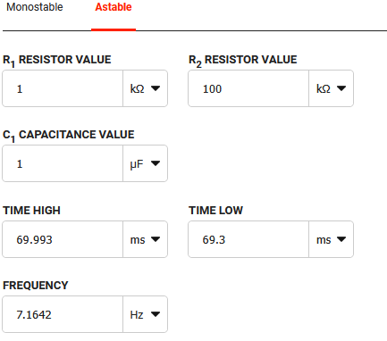
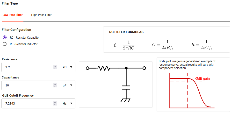
After reviewing the References above we'll make a slight modification based on the current state of our 555 timer frequency to give us better results on our Nano's plotter/scope. Employing Eater's R1=1 kΩ, R2=100 kΩ and C1=1 μF yields a 555 timer frequency of approximately 7.16 Hz as shown below left. Using Digikey's Filter Calculator we can design a series of identical low pass filters (3-Pole) to determine a value for a cutoff frequency close to this value while restricting our choices to resistor and capacitors values in our kits. The results are 2.2 kΩ for the three resistors and 10 μF for the three capacitors.
Find some time to construct this prototype before employing the code below to produce the plot shown above right.
| Digikey's 555 Frequency Calculator | Digikey's Low-Pass Filter Calculator |
|---|---|
 |
 |
// PROJECT  : My555SquaretoSineMonitor
// PURPOSE  : Monitors a 3-Pole Low Pass RC Filter to convert 555 square wave to a sinusoidal wave
// COURSE   : TEJ3M
// AUTHOR   : C. D'Arcy
// DATE     : 2025 11 19
// MCU      : 328p (Nano)
// STATUS   : Working
// REFERENCE: https://www.learningaboutelectronics.com/Articles/Square-to-sine-wave-converter-circuit.php

#define DIGITALCAP 2      //Monitor 555_3 on Nano_2
#define ANALOGCAP A0      //Monitors 3-Pole Low Pass Filter output
#define VCC 5.0           //Voltage supply maximum

void setup() {
  Serial.begin(9600);
  while (!Serial) {}
}

void loop() {
 // Serial.print("555_Pin_2:");  //Printing the Legend slows down the display
  Serial.print(VCC * analogRead(ANALOGCAP) / 1024);
  Serial.print(',');
 // Serial.print("555_Pin_3:");                   //Printing the Legend slows down the display
  Serial.print(VCC * digitalRead(DIGITALCAP));  //Scale it to stabilize the Serial plotting
  Serial.println();
}