Tasks
51. Create the project, TLExercise51. Determine the value of the second parameter of the Arduino's analogWrite(pin,value) function that results in the red LED's brightness level that is consistent with the yellow and green LEDs. Test it in sequence with the other two LEDs, using an efficient code strategy, to confirm. Think.
 50. Pulse-Width Modulation. You're acutely aware that the red LED appears brighter than the yellow or the green (a quick check of any LED datasheet confirms the reason) in this exercise we'll begin to explore how we can address the issue. First, Apple's Breathing LED.
- Use TL(11,12,13,GND). Open the Fade sketch (File > Examples > Basics). Change the led variable to 11. Upload the sketch and observe the effect the code has on the red LED.
- A few blogs have attempted to provide code for Apple's "patent" on the breathing LED effect. Try them out on pin 11 with the red LED. Sean Voisen, Breathing LED Circuit.
5. Variables.
6. #define directive
4. A close examination of the Arduino pins suggests an optimum location for single Traffic Light.
3. (Hard code everything, no directives, no variables) (pinMode(), digitalWrite(), delay()) Insert your Traffic Light device into digital pins 4-7, facing outwards.
- Create a new sketch (it should have your changes from the previous step) and Save As TLExercise1 in your (personal) Arduino Project folder.
- Using the most basic programming concepts, do your best to develop the same sequence of lights that cycle through on a traffic light. Use reasonable delay intervals between states.
2. Software. First, consider the strengths and weaknesses of the Blink sketch in the context of our ACES reference: Great Code. Since high efficiency and productivity are ACES' priorities, creation of a custom code template is a wise decision. Go to File > Examples > Basics and open the BareMinimum sketch. Modify the comments to reflect our ACES conventions and save the sketch to your Desktop. At the Finder level, locate the BareMinimum.ino file on your Desktop, copy it, and use it to replace the file by the same name inside the Examples folder of your Arduino application.

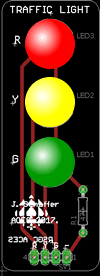
 1. Hardware. The result of Jasper S's (ACES '18) introduction to AutoDesk's EAGLE PCB Layout Application in the Winter of 2017 yielded a simple, but highly-effective, printed circuit board (PCB), for a standard Traffic Light. We are the fortunate recipients of his design work as you're going to use this device to develop great Arduino coding skills. (You, too, will be introduced to the design and production of printed circuit boards in this course and it's not too early to begin to think of a similar board that the ACES that follow you can use to their advantage).
Traffic Light Assembly and Testing. Before you get to the software side of these exercises you'll need to assemble and test your Traffic Light. Your Parts Kit consists of the following components,
- One Traffic Light PCB
- Three 10mm LEDs (red, yellow, and green)
- One 1/4W, 220Ω fixed resistor
- One, four-pin, right-angle male header
Roll over the image to the right to see how Jasper laid out the connections the board. Solder the PCB together making sure to orient the LEDs, and male headers, correctly. To confirm you have a working Traffic Light, insert the device into your Arduino into pins 11,12,13 & GND. Upload the Blink Example. Observe the result. Does this make sense?
 50. Pulse-Width Modulation. You're acutely aware that the red LED appears brighter than the yellow or the green (a quick check of any LED datasheet confirms the reason) in this exercise we'll begin to explore how we can address the issue. First, Apple's Breathing LED.
