| 2016-2017 TEI3M Challenges |
![]() BiColor LED Matrix. in the spring of 2014, T. Garrow (ACES '15) asked me what he could design and render on the 3D printer he received for Christmas. I suggested a double-sided jig that ACES could use to fabricate their own LED matrix and he did just that! A 'class set' of these jigs was impractical as the print time for a single one exceeds 2 hours. Fortunately, a company stepped in (Objex Unlimited) and printed two dozen for us in the spring of 2017, so the project was on for the first time!
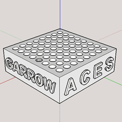
BiColor LED Matrix. in the spring of 2014, T. Garrow (ACES '15) asked me what he could design and render on the 3D printer he received for Christmas. I suggested a double-sided jig that ACES could use to fabricate their own LED matrix and he did just that! A 'class set' of these jigs was impractical as the print time for a single one exceeds 2 hours. Fortunately, a company stepped in (Objex Unlimited) and printed two dozen for us in the spring of 2017, so the project was on for the first time!
| Matrix Jig (T. Garrow, ACES '15) | Partially Assembled BiColor LED Matrix |
|---|---|
 |
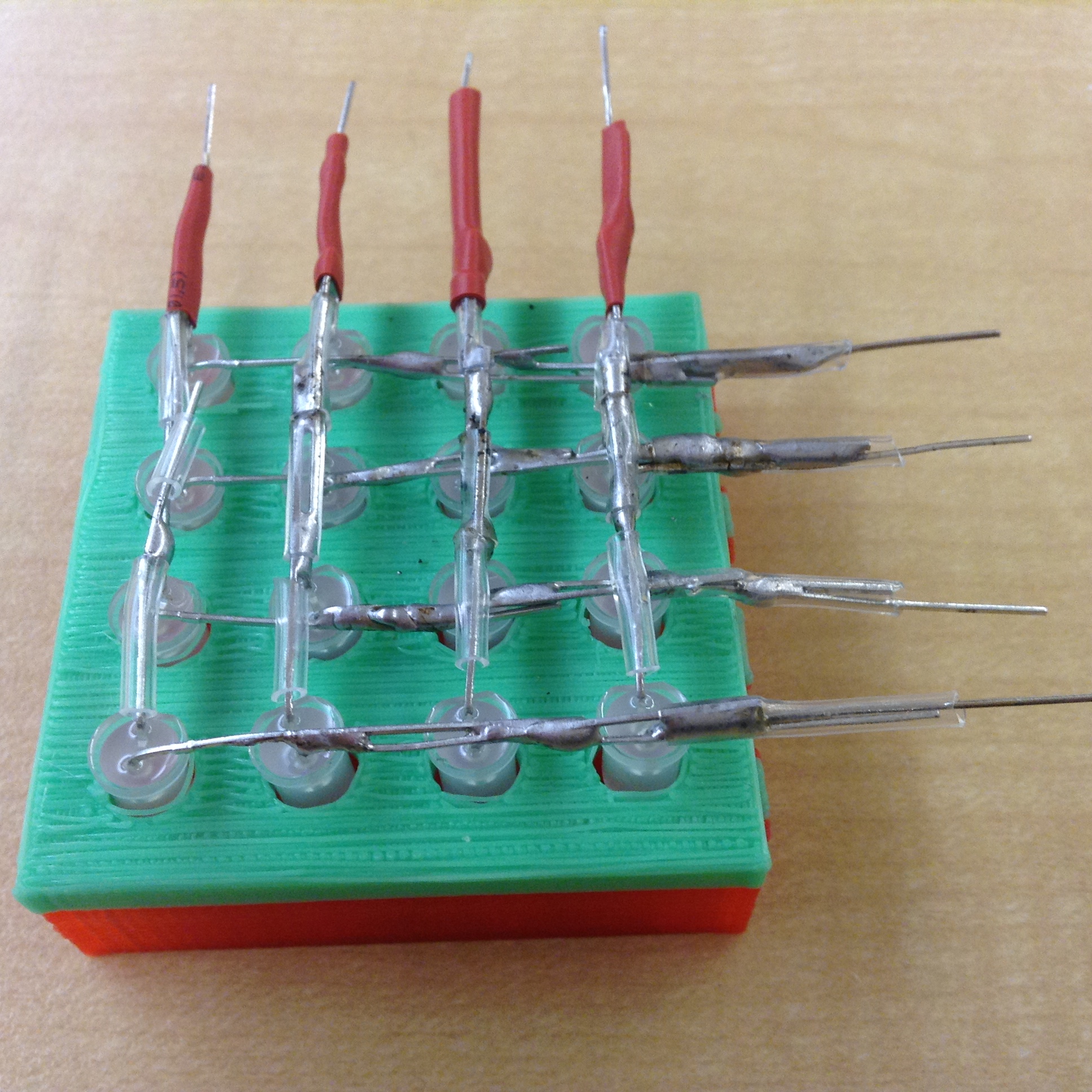 |
Take your time with this for better results. You may wish to review the numerous videos and tutorials available that describe how to construct and exercise 2D matrices and 3D cubes, both for the technique and the inspiration. For this task you will position the 16 bicolor LEDs into the jig you have been provided in, oriented in such a way that, when bent, sets of four longer leads overlap (since these a bicolor LEDs I hesitate to refer to them as anode and cathode). Solder each set of 4 together as in the photo, above right. At this point use a bench power supply set to 2V to confirm the integrity of all 16 LEDs. Make any adjustments to keep the leads as straight as possible.
Next, we do the same with the shorter leads, soldering in sets of 4, at right angles to their longer counterparts. Note. To avoid the possibility of electrical shorting, short, narrow heat shrink tubing slid oved the potential problem areas. Click the photo above right to see an example of my use of clear tubing. Again, use 2V to test all 16 LEDs. I added a length of heat-shrink on the ends for additional support.
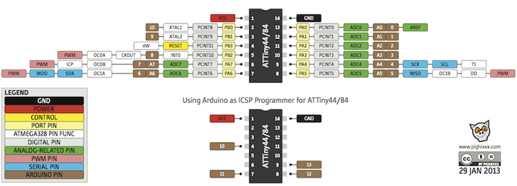
If you've made it this far you have 8 accessible leads, perfect for PORTA manipulation of the ATtiny84.
Task.
 Connect the 8 leads of your bicolor LED matrix to the PORTA pins of the ATtiny84.
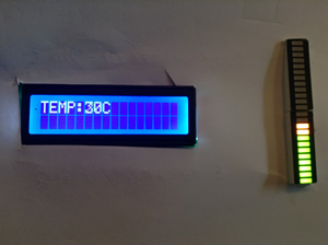 Challenge 3. Data Visualization. You have been given two new components: an additional 24LC256 EEPROM IC that has 48 temperature readings stored on it from 0 up to 72 and back down again, in multiples of 3, starting at address 0. As well you have been given a soldered-up Adafruit I2C BiColor 24-LED Bargraph.
Watch ![]() this video of the data on the EEPROM IC being displayed on the bargraph and an LCD module at 1-second intervals.
this video of the data on the EEPROM IC being displayed on the bargraph and an LCD module at 1-second intervals.
Your task in the next 50 minutes is to duplicate this video, exactly.
Task.
At the end of this period, submit only your Challenge3.ino source code to handin under the Subject Line: Challenge3. Code
Retain your two new componenents to assist you with further development of this project for your ER Summary due this Saturday (January 21) under the Subject Line: Challenge 3. ER
 (November) Challenge 2. 555. The 555 Timer IC is a versatile, low-cost IC that can provide a timed pulse. It's as popular today as it was when it was introduced in 1971. Even better: you have one in your kit. The 555 IC can operaate in a number of modes that include monostable, bistable or astable. Applications can be found for each.
Task.
 will be awarded on a first-come first-serve basis upon receipt of the email. Proposals will appear in the TEI4MForum conference so you can check which projects have been requested. I will review your proposal and let you know within 24 hours if you've got the green light or you need to go back to the drawing board. The deadline for proposals is this Saturday November 5th at midnight.
Checklist and Deadlines. I will update this table as the poject evolves.
ACE |
PROPOSAL Saturday November 5 |
PROTOTYPE Thursday November 10 |
PRESENTATION Tuesday November 22 |
ER SUMMARY Saturday November 26 |
|---|---|---|---|---|
P-C Ascherl |
Yes |
|||
S. Canavan |
Yes |
|||
K. Chepeha |
Yes |
|||
Q. Clarke |
Yes |
|||
D. Dadyburjor |
||||
R. Gajer |
Yes |
|||
D. Hofer |
Yes |
|||
O. Logush |
Yes |
|||
J. Longwell |
||||
A. MacDonald |
Yes |
|||
E. McAuliffe |
Yes |
|||
T. Morland |
||||
O. Murphy |
||||
E. Peterson |
Yes |
|||
J. Schaffer |
Yes |
|||
A. Sheeres-Palicpulle |
Yes |
|||
J. Stephenson-Smith |
7-Segment Something |
??? |
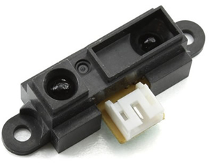 Challenge 1. Analog Sensor. In addition to your LCD Panel, you have been supplied with an Infrared Proximity Sensor made by Sharp (model: GP2Y0A41SK0F). NOTE: YOU ARE NOT TO MODIFY THIS PART IN ANY WAY AS IT WILL BE RETURNED TO MR. D. ON TUESDAY, IN ITS ORIGINAL CONDITION. The device claims to provide an analog output which varies from 3.1V (4cm) to 0.3V (30 cm) with a supply voltage between 4.5 and 5.5V DC. Having tested a few devices they vary somewhat from these specfications as could be expected.
Task.